
Bicycle hub with electricity generating mechanism and at least one lamp

Inactive Publication Date: 2009-12-08
SHIMANO INC
View PDF22 Cites 30 Cited by
  • Summary
  • Abstract
  • Description
  • Claims
  • Application Information

AI Technical Summary

Benefits of technology

[0010]The object of the present invention is to provide a bicycle hub that minimizes the trouble associated with lamp wiring from occurring in bicycle hubs having an electricity generating mechanism.
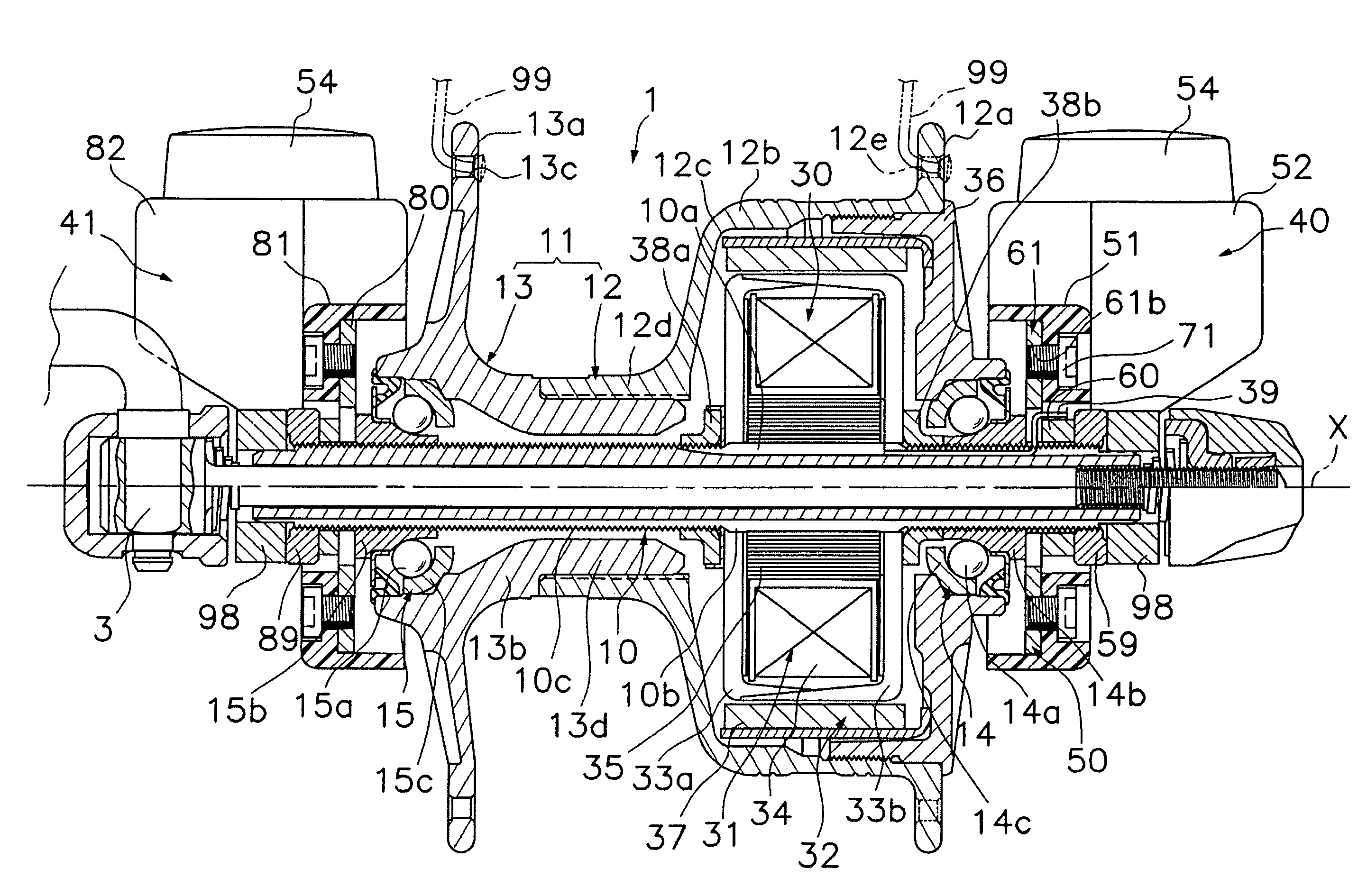
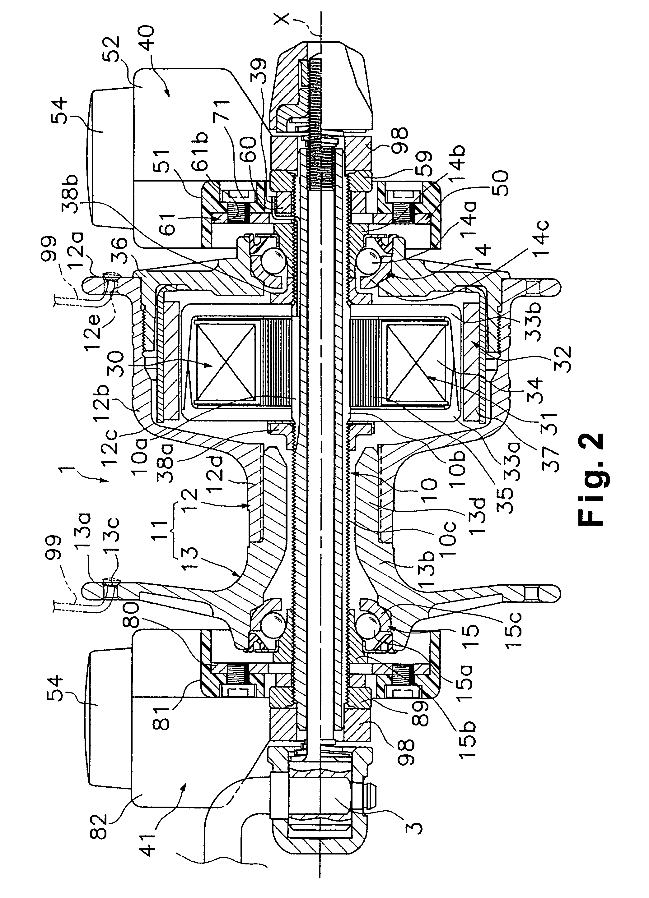
[0012]With this bicycle hub, the electricity generating mechanism generates electricity when the wheel rotates and the hub shell rotates relative to the hub shaft. The generated electric power is delivered to the least one lamp arranged on at least one end of the hub shell. Since the least one lamp is arranged on at least one end of the hub shell, the wiring from the electricity generating mechanism to the lamp is not easily exposed to the outside of the hub. Consequently, problems resulting from exposure of the wiring can be eliminated. Furthermore, since the wiring work can be completed at the bicycle hub manufacturing plant instead of the bicycle assembly plant, the bicycle assembly plant can focus solely on assembling the wheel using the bicycle hub and does not need to wire the lamp. Consequently, problems associated with wiring work can be eliminated. Also, the lamp(s) can be changed simultaneously with the wheel when the wheel is changed. Consequently, problems associated with handling the wiring when the wheel is changed can be eliminated. Moreover, the need to separately mount the lamp to the bicycle is eliminated because the lamp can be installed by mounting the bicycle hub to the bicycle frame.
[0016]In accordance with a fifth aspect of the present invention, the hub of the third or fourth aspect of the present invention is configured such that the two lamps are connected in series with respect to the electricity generating mechanism. With this bicycle hub, the switch circuitry and switch operation can be simplified because the two lamps can be turned on and off with one switch.
[0019]In accordance with an eighth aspect of the present invention, the hub of the seventh aspect of the present invention is configured such that the switch is configured to be turned on and off manually. With this bicycle hub, the switch circuitry is inexpensive because the switch is turned on and off manually.
[0021]With the present invention, since the lamp(s) is arranged on at least one end of the hub shell, it is difficult for the wiring from the electricity generating mechanism to the lamp(s) to become exposed to the outside of the hub. Consequently, problems resulting from exposure of the wiring can be eliminated. Furthermore, since the wiring work can be completed at the bicycle hub manufacturing plant instead of the bicycle assembly plant, the bicycle assembly plant can focus solely on assembling the wheel using the bicycle hub and does not need to wire the lamp. Consequently, problems associated with wiring work can be eliminated. Also, the lamp(s) can be changed simultaneously with the wheel when the wheel is changed. Consequently, problems associated with handling the wiring when the wheel is changed can be eliminated. Moreover, the need to mount the lamp to the bicycle is eliminated because the lamp can be mounted by mounting the bicycle hub to the bicycle frame.

Problems solved by technology

The wiring work associated with a conventional bicycle hub, such as disclosed in Japanese Laid-Open Patent Publication No. 2000-69731, is complicated because it is necessary to run wiring from the electricity generating mechanism installed inside the bicycle hub to the lamp at the bicycle assembly plant.
Furthermore, since the wiring to the lamp is exposed to the outside, it is possible for the wiring to catch on something and be broken.
Also, the work associated with changing the wheel is complicated because the wiring must be disconnected from the bicycle hub or the lamp when the wheel is removed and connected to the bicycle hub or the lamp when the wheel is installed.
Thus, such conventional hubs carry the risk of incurring problems associated with the wiring because the wiring must be run from the bicycle hub to the lamp and the wiring is exposed.
Since the least one lamp is arranged on at least one end of the hub shell, the wiring from the electricity generating mechanism to the lamp is not easily exposed to the outside of the hub.

Method used


Image

  • Bicycle hub with electricity generating mechanism and at least one lamp
  • Bicycle hub with electricity generating mechanism and at least one lamp
  • Bicycle hub with electricity generating mechanism and at least one lamp

Examples


Embodiment Construction

[0036]Selected embodiments of the present invention will now be explained with reference to the drawings. It will be apparent to those skilled in the art from this disclosure that the following descriptions of the embodiments of the present invention are provided for illustration only and not for the purpose of limiting the invention as defined by the appended claims and their equivalents.

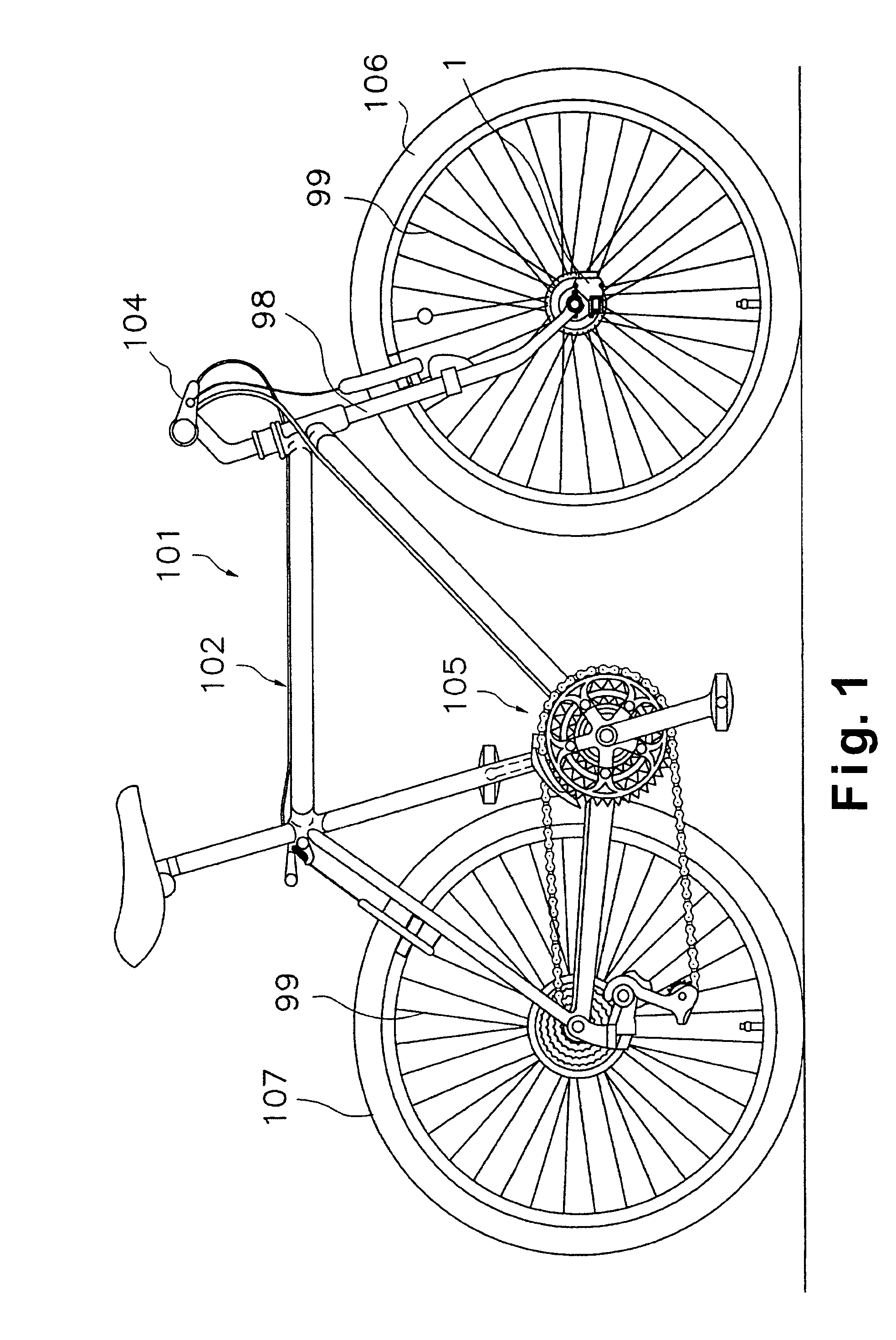
[0037]Referring initially to FIG. 1, a bicycle 101 is illustrated that is equipped with a front hub 1 in accordance with a first embodiment of the present invention. The bicycle 101 is provided with the following: a frame 102 that includes a front fork 98; a handlebar 104; a drive section 105 comprising a chain, pedals, etc.; and a front wheel 106 and rear wheel 107 having spokes 99.

[0038]The front hub 1 in accordance with the illustrated embodiment of the present invention is mounted to the tip end of the front fork 98. As shown in FIG. 2, the front hub 1 is provided with both an electricity gener...


PUM


Abstract

A bicycle hub includes a hub shaft, a hub shell, a bearing arrangement, an electricity generating mechanism and at least one lamp. The hub shaft is configured and arranged to be mounted in a non-rotatable manner to a bicycle frame. The hub shell has a hollow interior with the hub shaft being disposed in the hollow interior of the hub shell. The bearing arrangement is arranged between the hub shell and the hub shaft in such a manner that the hub shell can rotate freely with respect to the hub shaft. The electricity generating mechanism is arranged inside the hub shell and is configured to generate electricity in response to relative rotation of the hub shell with respect to the hub shaft. The lamp is arranged on at least one end of the hub shell and illuminated using electricity generated by the electricity generating mechanism.

Description

BACKGROUND OF THE INVENTION[0001]1. Field of the Invention[0002]The present invention generally relates to a bicycle hub. More particularly, present invention relates to a bicycle hub with an electricity generating mechanism.[0003]2. Background Information[0004]Bicycling is becoming an increasingly more popular form of recreation as well as a means of transportation. Moreover, bicycling has become a very popular competitive sport for both amateurs and professionals. Whether the bicycle is used for recreation, transportation or competition, the bicycle industry is constantly improving the various components of the bicycle.[0005]The bicycle hubs serve as the bicycle wheel axles. Generally, a bicycle hub includes a hub shaft mounted in a non-rotatable but freely detachable manner to the fork (frame) of a bicycle, a tubular hub shell mounted in a freely rotatable manner to the hub shaft, and a bearing that supports the hub shell in a freely rotatable manner on the hub shaft.[0006]Among ...

Claims


Application Information

Patent Timeline
IPC IPC(8): B62J6/12B60B27/06B60B27/00B62J6/00B62J6/02B62J6/20H02K7/18H02K21/22
CPCB62J6/001B62J6/20B62J6/12B62J6/01
Inventor FUJII, KAZUHIROUNO, KOJI
Owner SHIMANO INC
Learn More