
Automatic homing and track buffering device

a buffering device and automatic technology, applied in the direction of wing openers, constructions, door/window fittings, etc., can solve the problems of unstable positioning and deflection effect, failure of buffer homing, etc., to promote economic efficiency of manufacture and assembly, compact structure, and convenient, quick and economic manufacturing or assembly procedures

Active Publication Date: 2014-05-06
NAN JUEN INT CO LTD
View PDF20 Cites 17 Cited by
  • Summary
  • Abstract
  • Description
  • Claims
  • Application Information

AI Technical Summary

Benefits of technology

[0008]The object of the present invention is to provide an automatic homing and track buffering device with characteristics such as a compact structure and a convenient, quick and economic manufacture or assembly procedure positively promoting economic efficiency of manufacture and assembly.
[0009]The other object of the present invention is to provide an automatic homing and track buffering device with characteristics such as superior smooth, stable and qualified buffer action, minimized troubles and reliable durability in a homing buffer operation, promoted practicability, and product competitiveness.

Problems solved by technology

Furthermore, the track buffering structure relies on the deflected fastening member 30 to realize positioning, that is, the fastening member 30 under a tensile force deflects at two fastening grooves 15 but its positioning and deflection effect is unstable because the fastening groove 15 which must match but be restricted by the corresponding first resisting track 13 frequently results in the fastening member 30 pulled by the flexible member 6 and failure of buffer homing in case of accidental collision or strike.

Method used


Image

  • Automatic homing and track buffering device
  • Automatic homing and track buffering device
  • Automatic homing and track buffering device

Examples


Embodiment Construction

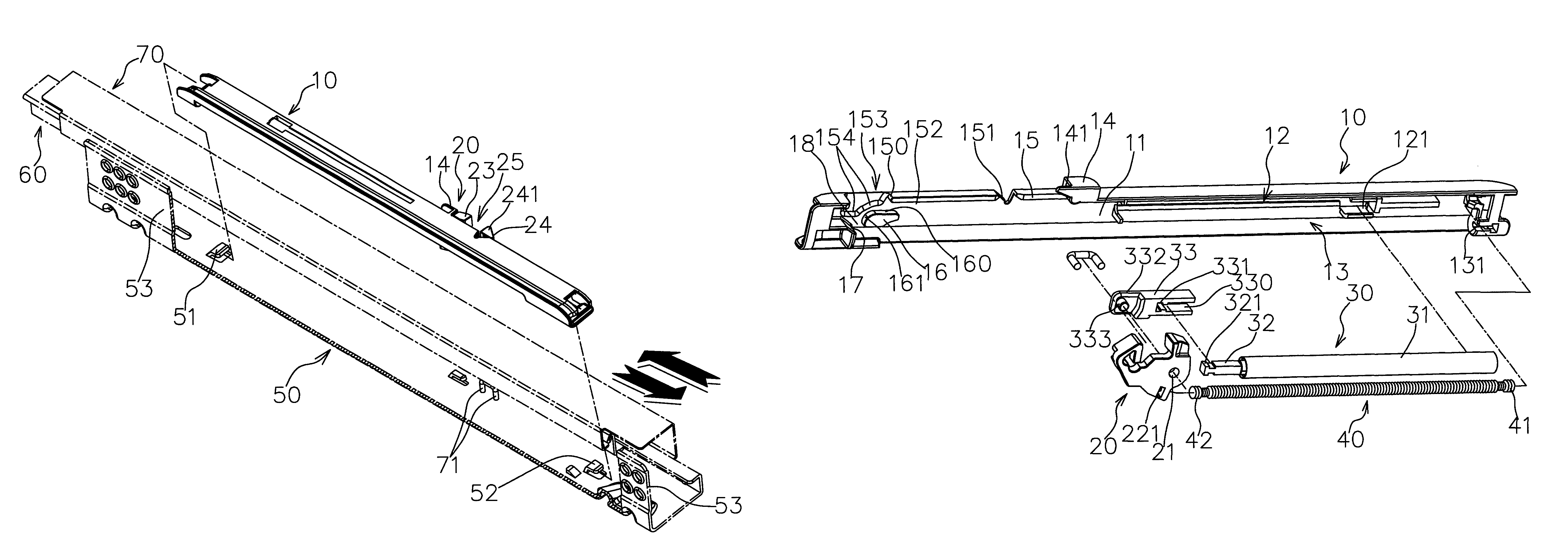
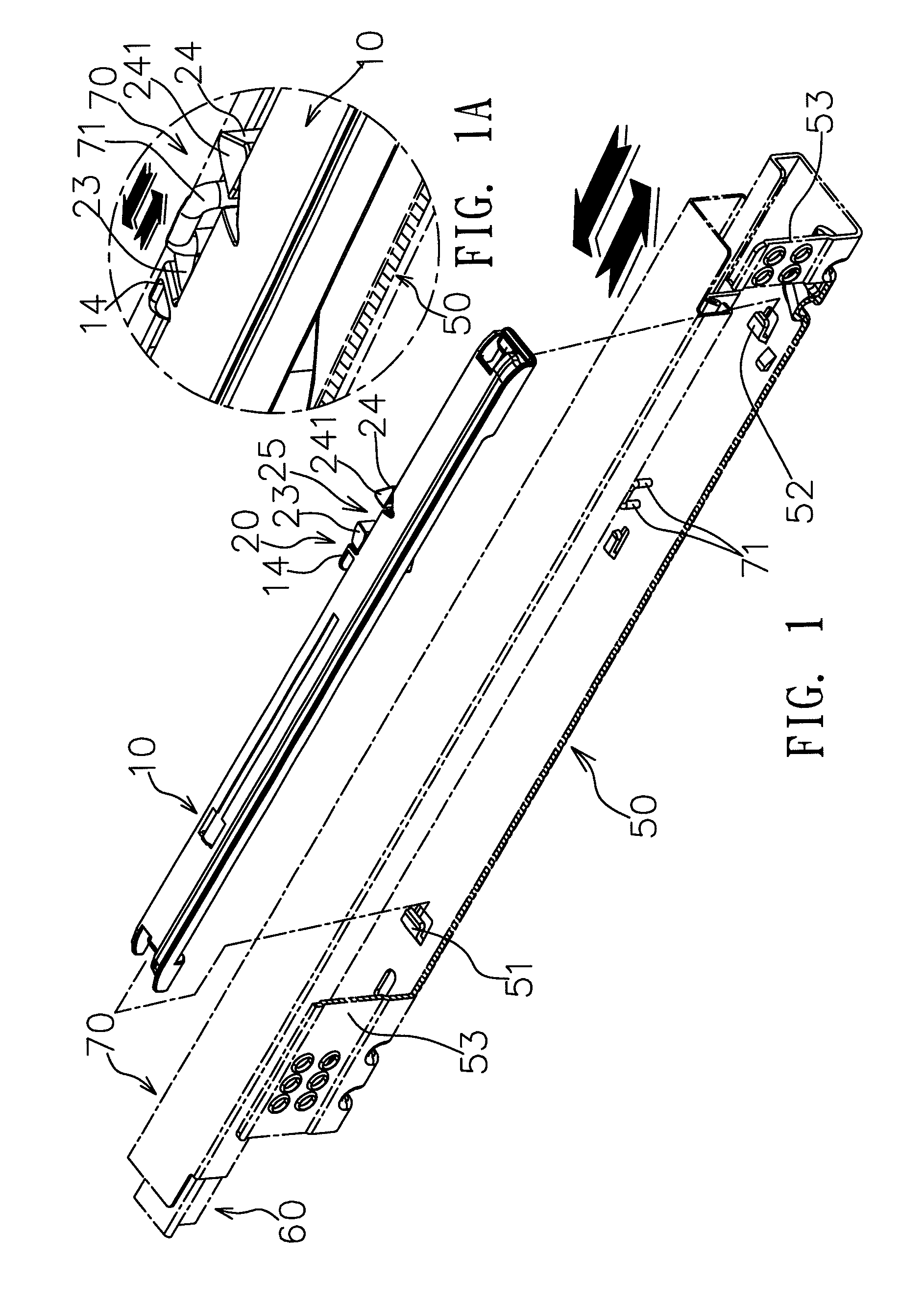
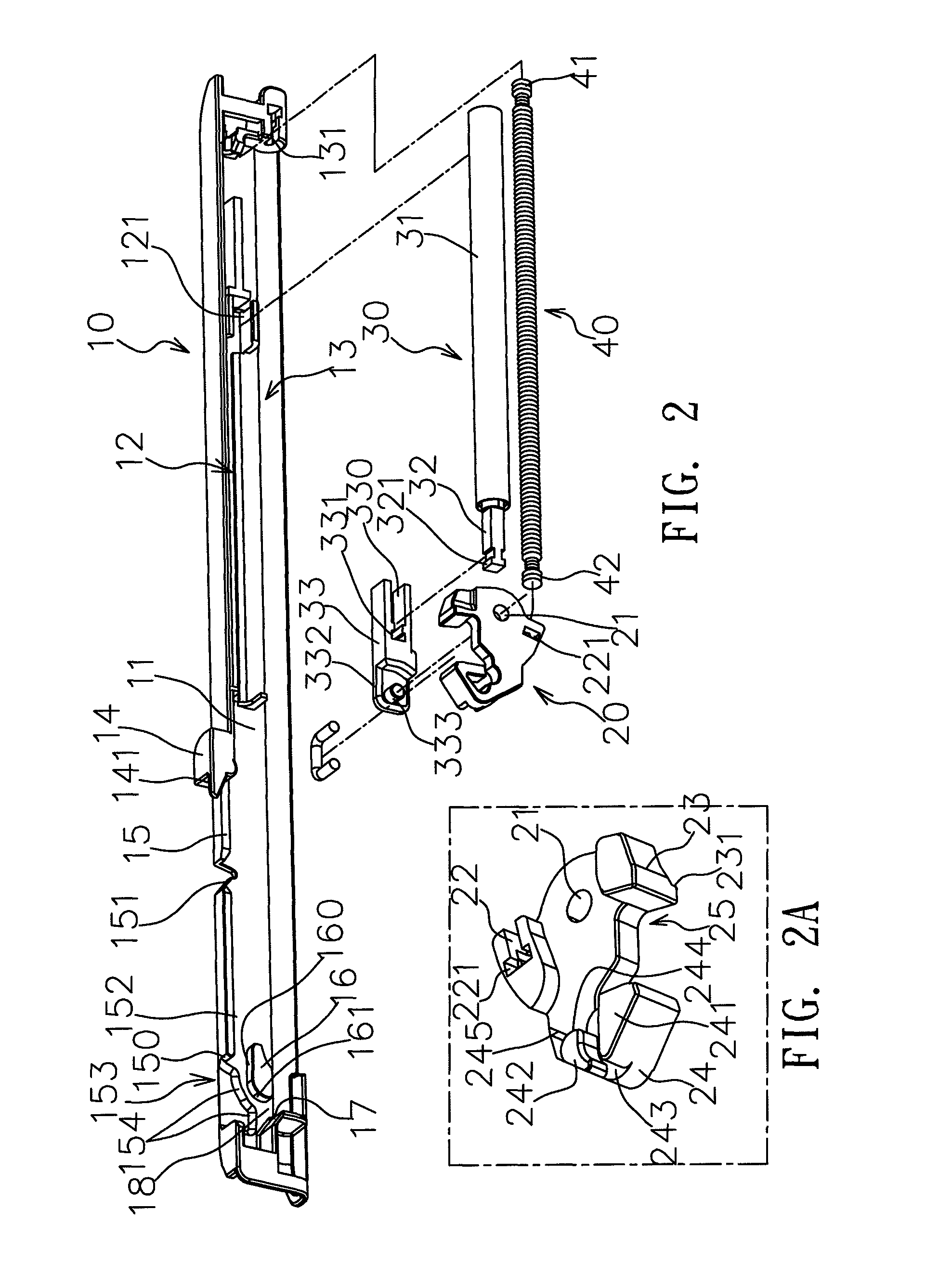
[0022]Referring to FIGS. 1, 1A, 2 and 2A which illustrate the present invention of an automatic homing and track buffering device comprises a buffer base 10, a swing member 20, a buffer member 30 and a flexible member 40. The buffer base 10 comprises a long tabular main base body 11 with a buffer groove space 12 and a flexible groove space 13 prepared at both sides wherein the buffer groove space 12 and the flexible groove space 13 are provided with a locating seat 121 and a locating part 131 at their rear ends, respectively. A positioning stopper 14 with a raised resisting part 141 protruding forward is mounted on the main base body 11 and opposite to one lateral edge of the buffer groove space 12. A slide margin 15 extends forward from the positioning stopper 14 at a lateral margin of the main base body 11 for further development of a marginal notch 151 and a marginal recess 152 wherein the marginal recess 152 has a slide terminal 150 developed ahead as a terminal of the extending...


PUM


Abstract

The present invention provides an automatic homing and track buffering device comprising a buffer base in which there are (a) a main base body with a buffer groove space and a flexible groove space prepared at both sides, a slide margin, and a revolving-resistant member having a slip resisting wall and a revolving-resistant wall in succession; (b) a buffer member; (c) a flexible member; (d) a swing member linking the buffer member's and the flexible member's front ends and provided with a push arm and a draw arm for development of an operating space in between wherein the draw arm has a first slider (external side) and a second slider with a curved part (internal side) for development of a slide groove in between.

Description

BACKGROUND OF THE INVENTION[0001]1. Field of the Invention[0002]The present invention relates to a buffering structure, particularly an automatic homing and track buffering device used in conjunction with slide tracks and featuring a compact structure which is of service to manufacture and assembly, minimizes failures, and realizes superior smooth operations and buffering effect.[0003]2. Description of the Related Art[0004]Cabinet lockers or drawers have been extensively applied in various storage implements. To realize a cabinet locker (drawer) which is conveniently pulled out, those slide tracks with functions for positioning and guidance are usually integrated into both laterals of a cabinet locker (drawer). For stable and quiet close of a cabinet locker (drawer), the slide tracks are further integrated with a buffering mechanism which takes advantage of a buffer action to prevent the cabinet from strong collision or noise and keep its longer service life and better operational q...

Claims


Application Information

Patent Timeline
Patent Type & Authority Patents(United States)
IPC IPC(8): A47B95/00
CPCA47B2210/0094A47B88/047E05Y2900/20E05F5/003E05Y2800/24E05F1/16A47B88/467
Inventor HUANG, KUO-SHENG
Owner NAN JUEN INT CO LTD
Learn More