Thermal activation method and thermal activation device for a heat-sensitive adhesive sheet

a technology of thermal activation and adhesive sheet, which is applied in the direction of identification means, instruments, furnaces, etc., can solve the problems of large electric current consumption resulting from driving every heating element with the standard driving energy, large size, weight and cost of large-capacity power sources, and reduce the area ratio of regions. , the effect of reducing the sum of driving energy

Inactive Publication Date: 2009-08-25
SEIKO INSTR INC
View PDF6 Cites 7 Cited by
  • Summary
  • Abstract
  • Description
  • Claims
  • Application Information

AI Technical Summary

Benefits of technology

[0014]This thermal activation method can make the heat-sensitive adhesive layer develop satisfactory adhesion through thermal activation while cutting the sum of energy supplied to achieve the thermal activation.
[0016]The sum of driving energy applied to one heat-sensitive adhesive sheet may be kept small by setting driving energy of each heating element equal to standard driving energy of each heating element and reducing the area ratio of regions in a heat-sensitive adhesive layer of the heat-sensitive adhesive sheet that are heated by opposing heating elements. This way, the sum of the driving energy can be reduced without fail. Another way to cut the sum of driving energy applied to one heat-sensitive adhesive sheet is to set driving energy of each heating element larger than standard driving energy of each heating element and reduce the area ratio of regions in a heat-sensitive adhesive layer of the heat-sensitive adhesive sheet that are heated by opposing heating elements. In this case also, the sum of the driving energy can be reduced by suitably adjusting the area ratio of regions that are heated by opposing heating elements and the driving energy of each heating element.
[0017]When a heat-sensitive adhesive layer of a heat-sensitive adhesive sheet is regarded as a matrix of dots each of which is sized to a heat generating portion of one heating element, it is preferable to give the size of 1 dot to the region that is not heated by any opposing heating element whereas, of 8 dots of regions surrounding this region, at least 4 dots of regions that are not adjacent to one another are heated by opposing heating elements. With this method, it is easy to make a heat-sensitive adhesive layer develop satisfactory adhesion through thermal activation while cutting the sum of driving energy. A particularly high reliability in adhesion development is obtained by heating, with opposing heating elements, all of the 8 dots of regions surrounding the region that is not heated by any opposing heating element.
[0018]A region in a heat-sensitive adhesive sheet that is to develop adhesion can have strong adhesion throughout when a heat-sensitive adhesive layer in this region is thermally activated throughout the region. If a heat-sensitive adhesive sheet has a region where adhesion should not be developed, a heating element that faces this region is not driven and no portion of a heat-sensitive adhesive layer in this region is thermally activated. In short, the thermal activation method described above is capable of creating an adhesive portion and a non-adhesive portion in the same heat-sensitive adhesive sheet through selective thermal activation, so that, for example, the adhesive portion is stuck fast to an article as a label and the non-adhesive portion is readily torn off as a copy of the label.
[0019]A thermal activation device for a heat-sensitive adhesive sheet according to the present invention is composed of a thermal head having plural heating elements which can be driven separately from one another; a conveying device for moving relative to the thermal head a heat-sensitive adhesive sheet which has a heat-sensitive adhesive layer in a direction intersecting a direction in which the heating elements of the thermal head are aligned; and a control device which synchronizes driving of the respective heating elements of the thermal head with movement of the heat-sensitive adhesive sheet relative to the thermal head and which stops, temporarily, at a given timing, driving a chosen few of the heating elements, and the thermal activation device creates in the heat-sensitive adhesive sheet a region that is not heated by any opposing heating element and thermally activates the heat-sensitive adhesive layer in this region with heat transmitted from surrounding regions. With this thermal activation device, the above-described thermal activation method of the present invention can readily be carried out.
[0020]The present invention is capable of thermally activating a heat-sensitive adhesive layer of a heat-sensitive adhesive sheet and thereby making the layer develop satisfactory adhesion while cutting the sum of energy spent for the thermal activation. Thermal activation according to the present invention is thus energy-efficient, and it is how the present invention reduces power consumption, electric current consumption, and heat accumulation. It is also possible for the present invention to raise the activation speed or, in the case where thermal activation is to be performed in succession, prolong the duration in which a thermal activation device is driven, by keeping power consumption and electric current consumption constant.

Problems solved by technology

A drawback thereof is great power consumption in the thermal activation process.
Another drawback is large electric current consumption resulting from driving every heating element with the standard driving energy, which represents the amount of energy used to obtain desired heat generation characteristics through normal driving of one heating element.
This means that a power source of large capacity is necessary in order to increase the speed of thermal activation and shorten the time it takes to thermally activate the entire surface of the heat-sensitive adhesive layer, and a large-capacity power source is large in size, weight and cost.
If a power source of relatively small capacity is employed to reduce electric current consumption, thermal activation slows down, prolonging the time to finish thermally activating the entire surface of the heat-sensitive adhesive layer and lowering the work efficiency.
Still another drawback is that a large amount of heat is accumulated because all the heating elements facing the heat-sensitive adhesive layer are driven and generate heat until the entire surface of the heat-sensitive adhesive sheet finishes passing the thermal head.
The large heat accumulation raises the temperature of the thermal head greatly and, for the purpose of protecting the thermal head, continuous use of the thermal head is limited to a short period of time.
The conventional thermal activation method thus has drawbacks of large power consumption, electric current consumption, and heat accumulation.
Prior art has never produced a thermal activation device that makes a heat-sensitive adhesive sheet develop strong adhesion while cutting power consumption, electric current consumption, and heat accumulation.

Method used


Image

  • Thermal activation method and thermal activation device for a heat-sensitive adhesive sheet
  • Thermal activation method and thermal activation device for a heat-sensitive adhesive sheet
  • Thermal activation method and thermal activation device for a heat-sensitive adhesive sheet

Examples


first embodiment

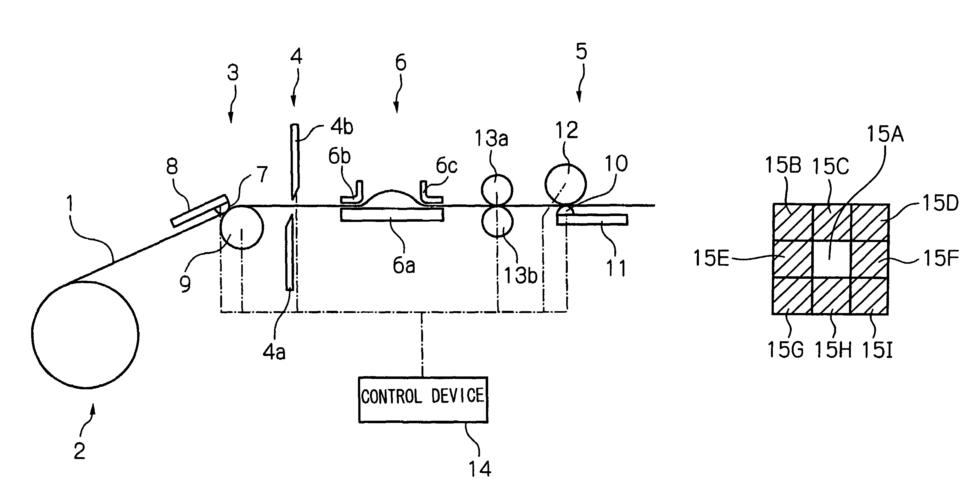
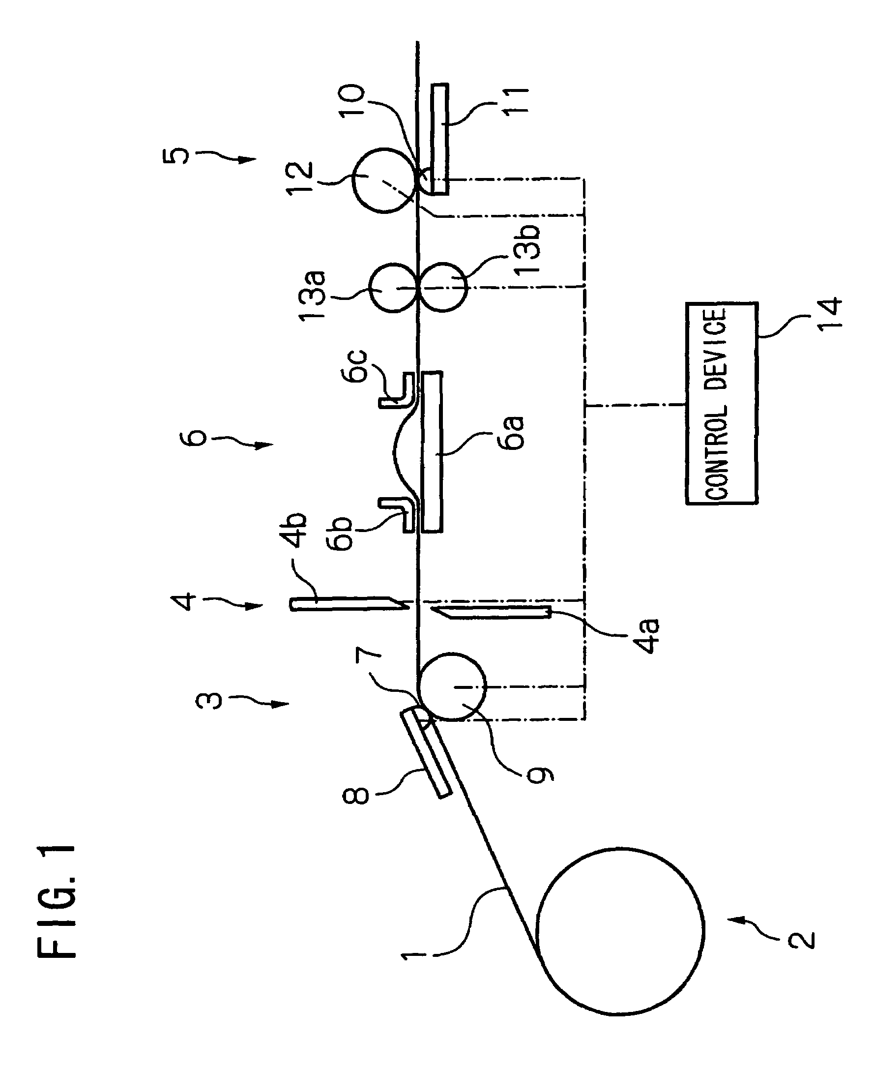
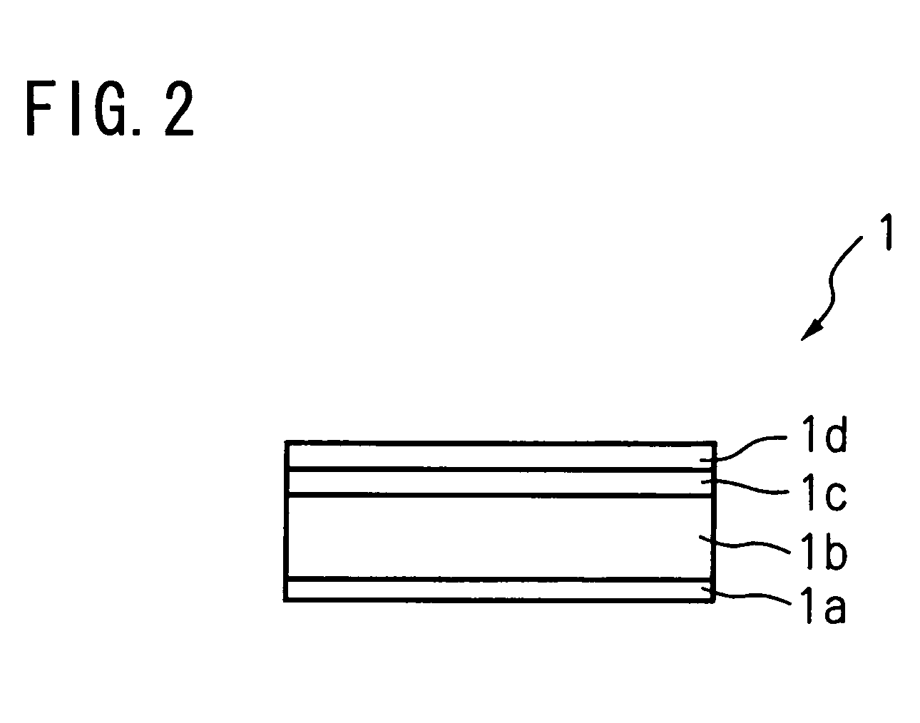
[0045]A brief description will be given first on the basic structure of a printer for a heat-sensitive adhesive sheet in which a thermal activation device of this embodiment is incorporated. As schematically shown in FIG. 1, this printer for a heat-sensitive adhesive sheet is composed of a roll housing unit 2 for holding a heat-sensitive adhesive sheet 1 that is wound into a roll; a printing unit 3 for printing on a printable layer 1d (see FIG. 2) of the heat-sensitive adhesive sheet 1; a cutter unit 4 for cutting the heat-sensitive adhesive sheet 1 into a given length; a thermal activation unit 5 which thermally activates a heat-sensitive adhesive layer 1a (see FIG. 2) of the heat-sensitive adhesive sheet 1 and which constitutes the main part of the thermal activation device of this embodiment; a guide unit 6 for guiding the heat-sensitive adhesive sheet 1 along a path from the cutter unit 4 to the thermal activation unit 5; and other components. While in practice the heat-sensitiv...

second embodiment

[0074]The second embodiment of the present invention will be described next. This embodiment also employs the same printer for a heat-sensitive adhesive sheet (see FIG. 1) that is used in the first embodiment to perform the thermal activation described above. The difference between the two embodiments is that the driving pattern and driving energy of the heating elements 10 are set differently. Given below is a description on the driving pattern and driving energy for thermal activation in this embodiment. Other aspects of the thermal activation method, the structure of the thermal activation device, and the like are identical with those in the first embodiment and descriptions thereof are omitted here.

[0075]In this embodiment, as shown in FIG. 9A, regions that are not directly heated by any of the opposing heating elements 10 (other regions than hatched regions) and regions that are directly heated by the opposing heating elements 10 (hatched regions) are alternated without excepti...


PUM

PropertyMeasurementUnit
temperatureaaaaaaaaaa
heat-sensitiveaaaaaaaaaa
heat-aaaaaaaaaa

Abstract

A thermal head has heating elements that can be selectively driven independently from one another during a driving operation to directly heat, and thereby thermally activate, regions of a heat-sensitive adhesive layer of a heat-sensitive adhesive sheet while the heat-sensitive adhesive sheet is moved relative to the thermal head with the heating elements disposed in opposing relation to the respective regions of the heat-sensitive adhesive layer. All but at least one of the heating elements are selectively driven so that (a) a preselected region of the heat-sensitive adhesive layer disposed in opposing relation to each non-driven heating element is not directly heated, and thereby not directly thermally activated, by the non-driven heating element, (b) the regions of the heat-sensitive adhesive layer disposed in opposing relation to the respective driven heating elements are directly heated, and thereby directly thermally activated, by the respective driven heating elements, and (c) each preselected region of the heat-sensitive adhesive layer opposed to a non-driven heating element is thermally activated with heat transmitted from surrounding directly heated regions of the heat-sensitive adhesive layer of the heat-sensitive adhesive sheet.

Description

BACKGROUND OF THE INVENTION[0001]1. Field of the Invention[0002]The present invention relates to a method of thermally activating a heat-sensitive adhesive sheet with a heat-sensitive adhesive layer, and a thermal activation device therefor.[0003]2. Description of the Related Art[0004]Heat-sensitive adhesive sheets with a heat-sensitive adhesive layer that develops adhesion when heated, as those disclosed in JP 11-79152 A and JP 2003-316265 A, have been in practical use for some time now. Such heat-sensitive adhesive sheets have advantages including being easy to handle since the sheets are not adhesive prior to heating and producing no factory wastes since they do not need release paper. A thermal head, which is usually employed as a printing head in a thermal printer, is sometimes used to heat this type of heat-sensitive adhesive sheet and to thereby make its heat-sensitive adhesive layer develop adhesion. This is advantageous particularly when a heat-sensitive adhesive sheet is p...

Claims


Application Information

Patent Timeline
Patent Type & Authority Patents(United States)
IPC IPC(8): B65C9/25B65C9/24F27B9/36F27B9/40C09J7/02B41J2/32B41J3/407B41J15/00B41J15/04C09J5/06G09F3/10
CPCB41J2/32B41J3/4075B41J15/046B65C9/25B41J15/005Y10T156/17
Inventor KOHIRA, HIROYUKITAKAHASHI, MASANORISATO, YOSHINORIHOSHINO, MINORUOBUCHI, TATSUYA
Owner SEIKO INSTR INC
Why Eureka
Try Eureka