
Dynamic load detection for a clothes washer

a dynamic load and clothes washer technology, applied in other washing machines, domestic applications, textiles and papermaking, etc., can solve the problems of severe damage to the washing machine, inability to detect the load of the inability to move the basket and the entire washing machine, so as to reduce the vibration, save time and energy, and bring more loads

Inactive Publication Date: 2009-09-01
WHIRLPOOL CORP
View PDF22 Cites 23 Cited by
  • Summary
  • Abstract
  • Description
  • Claims
  • Application Information

AI Technical Summary

Benefits of technology

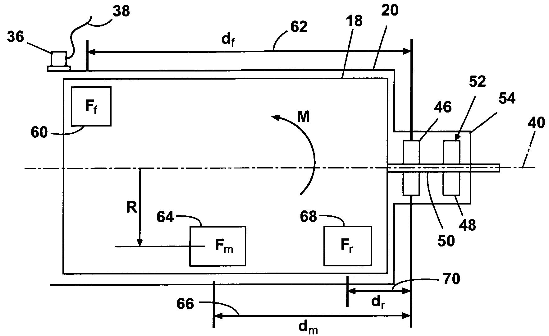
[0026]A method for controlling the spin cycle in an automatic clothes washer. The clothes washer comprises an imperforate tub, a perforate basket located within the tub, a bearing assembly carried by the tub, a drive shaft rotationally supported in the bearing assembly and coupled to the basket to define a rotational axis of the basket, a drive assembly rotating the drive shaft, and a controller operably to the drive assembly, with the controller controlling the drive mechanism to control the spin rate of the basket according to a spin cycle. The method comprises sensing a moment acting on the bearing, and controlling the spin rate of the basket in response to the sensed moment. The objective for this invention is to reduce vibration, save time and energy, and bring more loads up to highest speeds.

Problems solved by technology

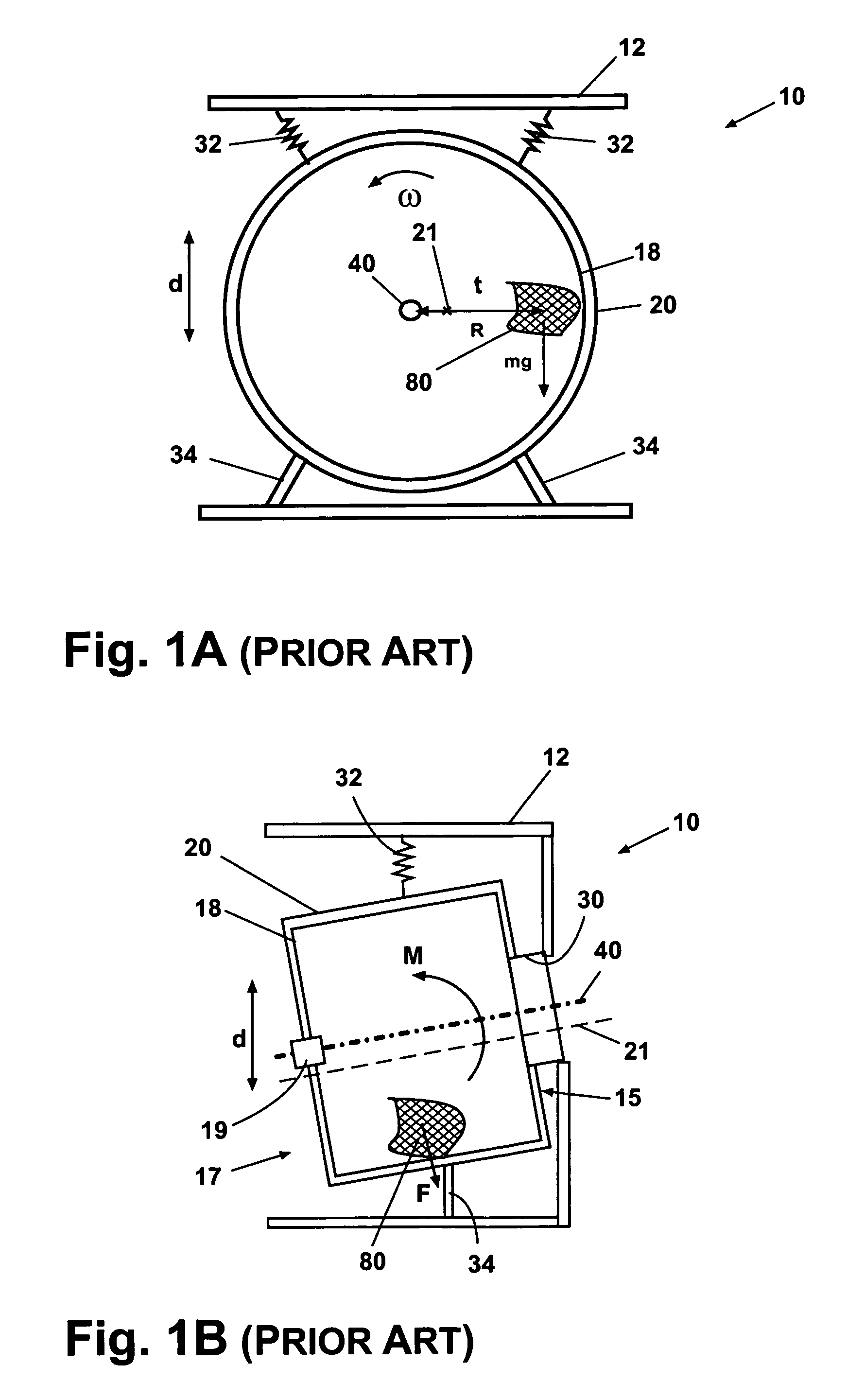
But when clothing and water are not evenly distributed about the axis of the basket, an imbalance condition occurs.
At such high speeds, an imbalance can result in unacceptable vibratory movement of the basket and the entire washing machine.
The washing machine can be affected severely enough that it will “walk” across the floor and cause floor vibration.
The tub and basket can move enough such that the tub reaches the limit of its suspension and / or contacts the surrounding cabinet structure, referred to as “cabinet hits,” with consequent noise and possible damage.
Higher spin speeds coupled with larger capacity baskets aggravates imbalance problems in washing machines, especially in horizontal axis washers.
Imbalance conditions become harder to accurately detect and correct.
If the moment is high enough, the wobble can be unacceptable.
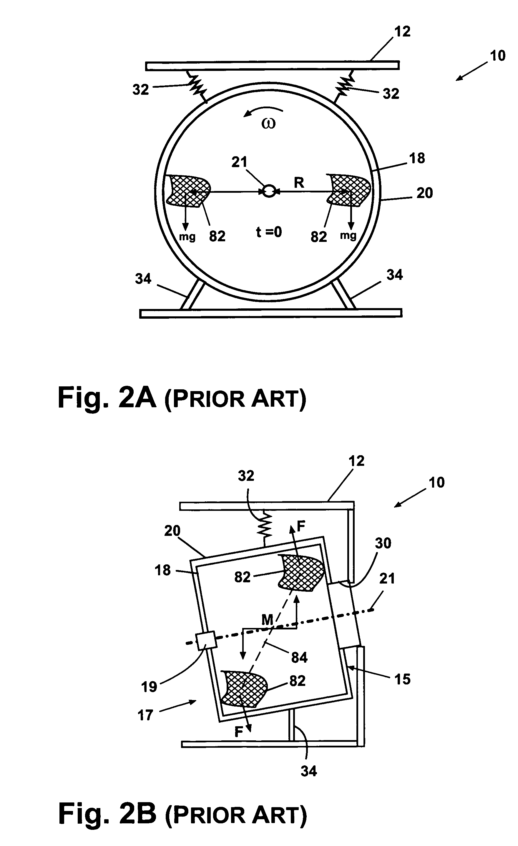
However, dynamically, there is a significant difference when an imbalance load is in the front or at the back.
The area above this limit curve is the unacceptable imbalance area at a given spinning speed.
The imbalance at the front has larger dynamic effects that result in larger vibration.
A consequent result is unacceptable vibration and noise at high speed due to the underestimate.
Many efforts have been put for detecting location of single static imbalance, as well as coupled dynamic imbalance but not successful.
Many solutions have been advanced for detecting and correcting single static imbalance but correction is generally limited to aborting the spin, reducing the spin speed, or changing the loads in or on the basket.
Detection presents the more difficult problem.
But there is no correlation between static imbalance conditions and dynamic imbalance conditions; applying a static imbalance algorithm to torque fluctuations will not accurately detect a dynamic imbalance.
Conversely, an imbalance condition caused by a rear off balance load (see FIG. 4) will be overestimated by existing systems for measuring static imbalances.
Moreover, speed, torque, current, watts in the motor can all fluctuate for reasons unrelated to basket imbalance.
A second source of friction in a given washing machine is related to load size and any imbalance condition.
However, it is not entirely accurate for horizontal axis washing machines because it does not accurately ascertain the various dynamic imbalance conditions and does not ascertain information related to load size.
Another problem in reliably detecting imbalances in production washers regardless of axis is presented by the fact that motors, controllers, and signal noise vary considerably from unit to unit.
Thus, for example, a change in motor torque in one unit may be an accurate correlation to a given imbalance condition in that unit, but the same change in torque in another unit may not be an accurate correlation for the same imbalance condition.
In fact, the problems of variance among units and signal noise are common to any appliance where power measurements are based on signals that are taken from electronic components and processed for further use.
However such technologies cannot detect coupled dynamic loads, are unable to base corrective action on the location of the imbalance, overcompensate for load imbalances at the rear of the basket and under compensate for load imbalances at the front of the basket.
Furthermore, the use of accelerometers typically does not enable the determination of the imbalance location, or the severity of vibration at higher speeds.

Method used


Image

  • Dynamic load detection for a clothes washer
  • Dynamic load detection for a clothes washer
  • Dynamic load detection for a clothes washer

Examples


Embodiment Construction

[0040]Referring to the Figures, and in particular to FIG. 6, an embodiment of the invention illustrated as an automatic clothes washer 10 according to the invention is shown having a cabinet 12 with a front portion 15 and a rear portion 17. The front portion 15 has an opening 30 closeable by a door 16. The clothes washer 10 described herein shares many features of a well-known clothes washer, and will not be described in detail except as necessary for a complete understanding of the invention.

[0041]The cabinet 12 encloses a perforate rotatable basket 18 within a stationary imperforate tub 20. The cabinet 12 also mounts a control panel 14 having control elements, such as switches, dials, buttons, and the like, operably coupled with a solid-state microprocessor-based controller 22 for controlling the operation of the clothes washer 10. The basket 18 defines an axis of rotation 40, a generally vertical axis 56, and a generally horizontal axis 58. The vertical axis 56 and the horizontal...


PUM


Abstract

A method for controlling the spin cycle in an automatic clothes washer. The clothes washer comprises an imperforate tub, a perforate basket located within the tub, a bearing assembly carried by the tub, a drive shaft rotationally supported in the bearing assembly and coupled to the basket to define a rotational axis of the basket, a drive assembly rotating the drive shaft, and a controller operably to the drive assembly, with the controller controlling the drive mechanism to control the spin rate of the basket according to a spin cycle. The method comprises sensing a moment acting on the bearing, and controlling the spin rate of the basket in response to the sensed moment.

Description

BACKGROUND OF THE INVENTION[0001]1. Field of the Invention[0002]The invention relates generally to automatic clothes washers, and, more specifically relates to an automatic clothes washer and method for determining an unbalanced condition, especially a dynamic unbalanced condition.[0003]2. Description of the Related Art[0004]Washing machines utilize a generally cylindrical perforated basket for holding clothing and other articles to be washed that is rotatably mounted within an imperforate tub mounted for containing the wash liquid, which generally comprises water, detergent or soap, and perhaps other constituents. In some machines the basket rotates independently of the tub and in other machines the basket and tub both rotate. Typically, an electric motor drives the basket. Various wash cycles introduce into the clothing and extract from the clothing the wash liquid, usually ending with one or more spin cycles where final rinse water is extracted from the clothes by spinning the ba...

Claims


Application Information

Patent Timeline
Patent Type & Authority Patents(United States)
IPC IPC(8): D06F33/00D06F35/00D06F33/48
CPCD06F37/203D06F33/48D06F2103/26D06F2103/46
Inventor XIE, MARK MINGJUNSLABBEKOORN, SCOTT D.
Owner WHIRLPOOL CORP
Learn More