Method of measuring the performance of a prosthetic foot

a technology of prosthetic feet and performance indicators, applied in the field of prosthetic feet, can solve the problems of difficult to illustrate the performance of prosthetic foot designs based on said methods, and achieve the effect of superior performan

Active Publication Date: 2009-09-01
OSSUR HF
View PDF140 Cites 58 Cited by
  • Summary
  • Abstract
  • Description
  • Claims
  • Application Information

AI Technical Summary

Problems solved by technology

However, it is often difficult to illustrate the performance of prosthetic foot designs based on said methods, or to provide a user with a simple and easy to understand performance comparison of prosthetic foot designs.

Method used


Image

  • Method of measuring the performance of a prosthetic foot
  • Method of measuring the performance of a prosthetic foot
  • Method of measuring the performance of a prosthetic foot

Examples


Embodiment Construction

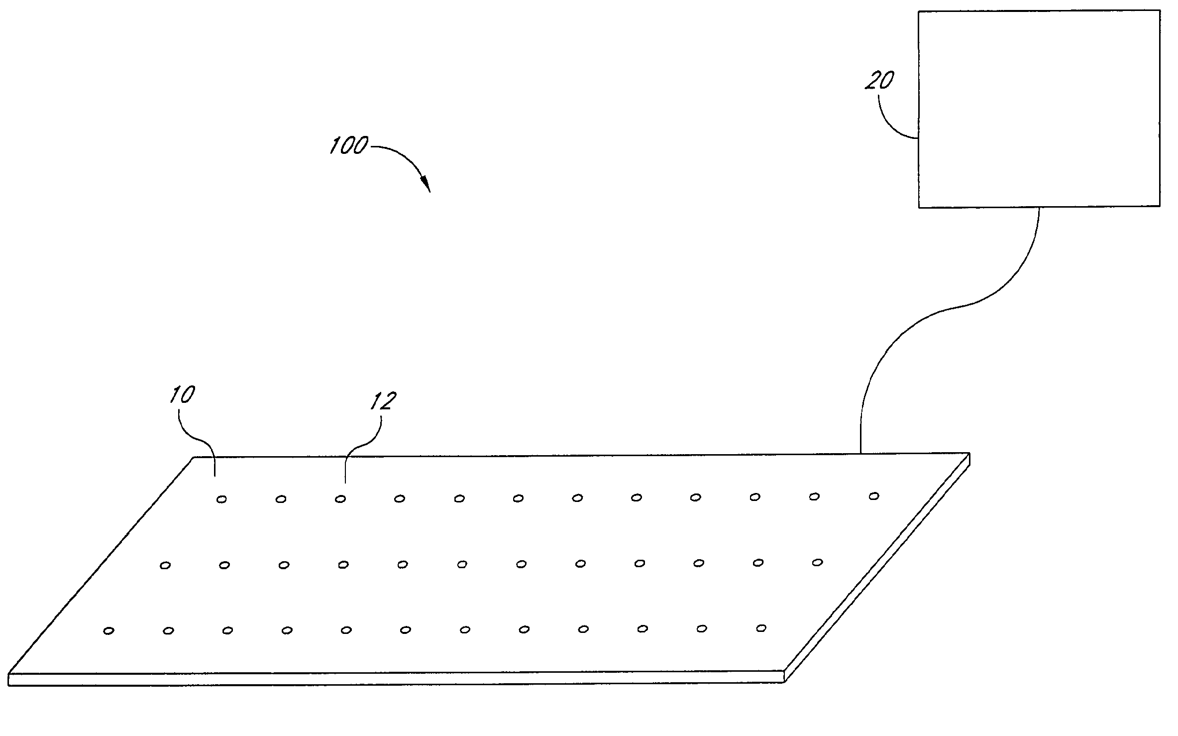
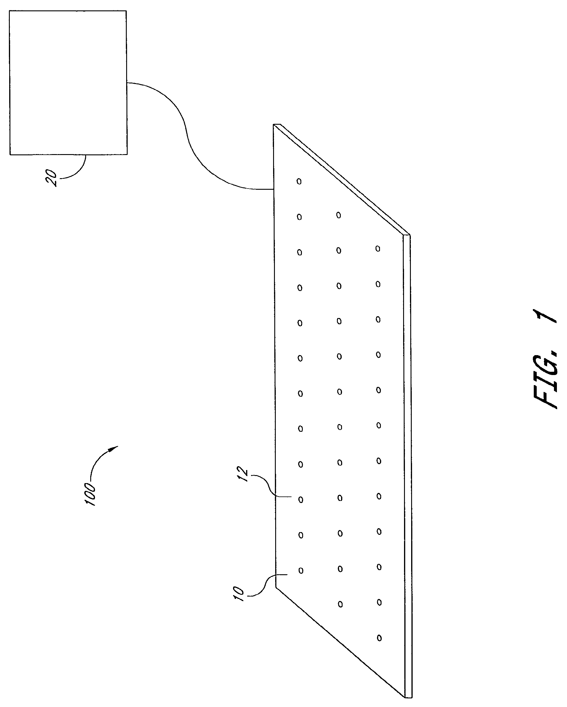
[0017]FIG. 1 illustrates a system 100 for measuring the performance of a prosthetic foot or other leg support device. In one embodiment, the system 100 can be used to measure the performance of an orthotic device disposed on a human foot, such as a foot or ankle brace. In still another embodiment, the system 100 can be used to measure the performance of a prosthetic knee. Accordingly, the scope of the invention herein disclosed should not be limited by the particular disclosed embodiments described below. Moreover, the embodiments below are not limited to prosthetic feet but can be applied to other leg support devices, including orthotic devices.

[0018]As shown in FIG. 1, The system 100 preferably comprises a surface 10, wherein the surface 10 includes a plurality of sensors 12 configured to sense a force exerted thereon by the prosthetic foot. The sensors 12 communicate with a computer 20, which obtains the sensed forces from the sensors 12. In one preferred system, the surface 10 c...


PUM


Abstract

A method of measuring the performance of a prosthetic foot includes obtaining a pressure distribution of the prosthetic foot during a motion of the prosthetic foot and determining whether the pressure distribution falls within a preselected range of performance values for the prosthetic foot. The pressure distribution comprises a trajectory illustrating the progression of a center of pressure of the prosthetic foot during motion. A prosthetic foot can also be designed to approximate a pressure distribution corresponding to a preselected range of performance values.

Description

PRIORITY INFORMATION[0001]This application claims priority to U.S. Provisional Patent Application No. 60 / 575,142 filed May 28, 2004, and U.S. Provisional Patent Application No. 60 / 590,717, filed Jul. 23, 2004. This application is also a continuation-in-part of U.S. application Ser. No. 10 / 944,436, filed Sep. 17, 2004 now U.S. Pat. No. 7,347,877.BACKGROUND OF THE INVENTIONS[0002]1. Field of the Inventions[0003]The present embodiments generally relate to prosthetic feet, and more particularly, to methods of measuring the performance of prosthetic feet.[0004]2. Description of the Related Art[0005]Methods for measuring the performance of prosthetic feet are known in the art. Conventional methods include comparing the gait characteristics of different prosthetic foot designs, as well as comparing the gait characteristic of a prosthetic foot with the natural gait of a human foot. However, it is often difficult to illustrate the performance of prosthetic foot designs based on said methods,...

Claims


Application Information

Patent Timeline
Patent Type & Authority Patents(United States)
IPC IPC(8): G01D7/00
CPCA61F2/66A61F2/76A61B5/1038A61F2250/0084A61F2/6607A61F2002/3007A61F2002/30434A61F2002/30708A61F2002/5001A61F2002/5003A61F2002/5007A61F2002/5009A61F2002/503A61F2002/5055A61F2002/5066A61F2002/6628A61F2002/6635A61F2002/6642A61F2002/665A61F2002/6685A61F2002/7635A61F2002/769A61F2002/7695A61F2220/0041A61F2250/0018A61F2250/0029A61F2250/0036A61B5/4528A61F2002/30433
Inventor CLAUSEN, ARINBJORN V.DE ROY, KIM
Owner OSSUR HF
Why Eureka
Try Eureka