Gear modification that enables direct off-center engagement

a technology of off-center engagement and gear modification, which is applied in the direction of gearing, gearing details, hoisting equipment, etc., can solve the problems of limited torque that can be transmitted, drawers or assemblies may not position or lock correctly relative to the slot, and damage to the top lands of both teeth, so as to reduce the probability of tooth-to-tooth contact, reduce the reducing the bad effect of tooth-to-tooth conta

Inactive Publication Date: 2009-09-01
XEROX CORP
View PDF24 Cites 22 Cited by
  • Summary
  • Abstract
  • Description
  • Claims
  • Application Information

AI Technical Summary

Benefits of technology

[0009]One method of avoiding the tooth-to-tooth contact is to provide narrow teeth. Although the probability for tooth-to-tooth contact is decreased, tooth-to-tooth contact can still occur. Another method of mitigating the bad effects of the tooth-to-tooth contact is to provide a spring loaded or a gravity loaded idler gear that pivots around the center of a first gear. The idler gear pivots around the center of a first gear and moves out of the way of the teeth of the second gear in order to avoid the high forces associated with tooth-to-tooth contact. Spring-loaded shafts that allow the gears to take the impact of the tooth-to-tooth contact can also be used. As a result, the torque that can be transmitted is limited because of the spring. Furthermore, manufacturing costs are increased by using the idler gear or the spring-loaded shafts. Furthermore, in both cases the size of the gear mechanism is increased in order to accommodate the additional structure.
[0010]Accordingly, the invention thus provides, among other things, a method and apparatus that allows direct engagement that is simple, inexpensive, increases the life span of the two gears, and allows assemblies to be located properly.

Problems solved by technology

Damage can thus occur to the top lands of both teeth because of the force created by the tooth-to-tooth contact.
As such, the drawer or assembly may not position or lock correctly relative to the slot.
As a result, the torque that can be transmitted is limited because of the spring.
Furthermore, manufacturing costs are increased by using the idler gear or the spring-loaded shafts.

Method used


Image

  • Gear modification that enables direct off-center engagement
  • Gear modification that enables direct off-center engagement
  • Gear modification that enables direct off-center engagement

Examples


Embodiment Construction

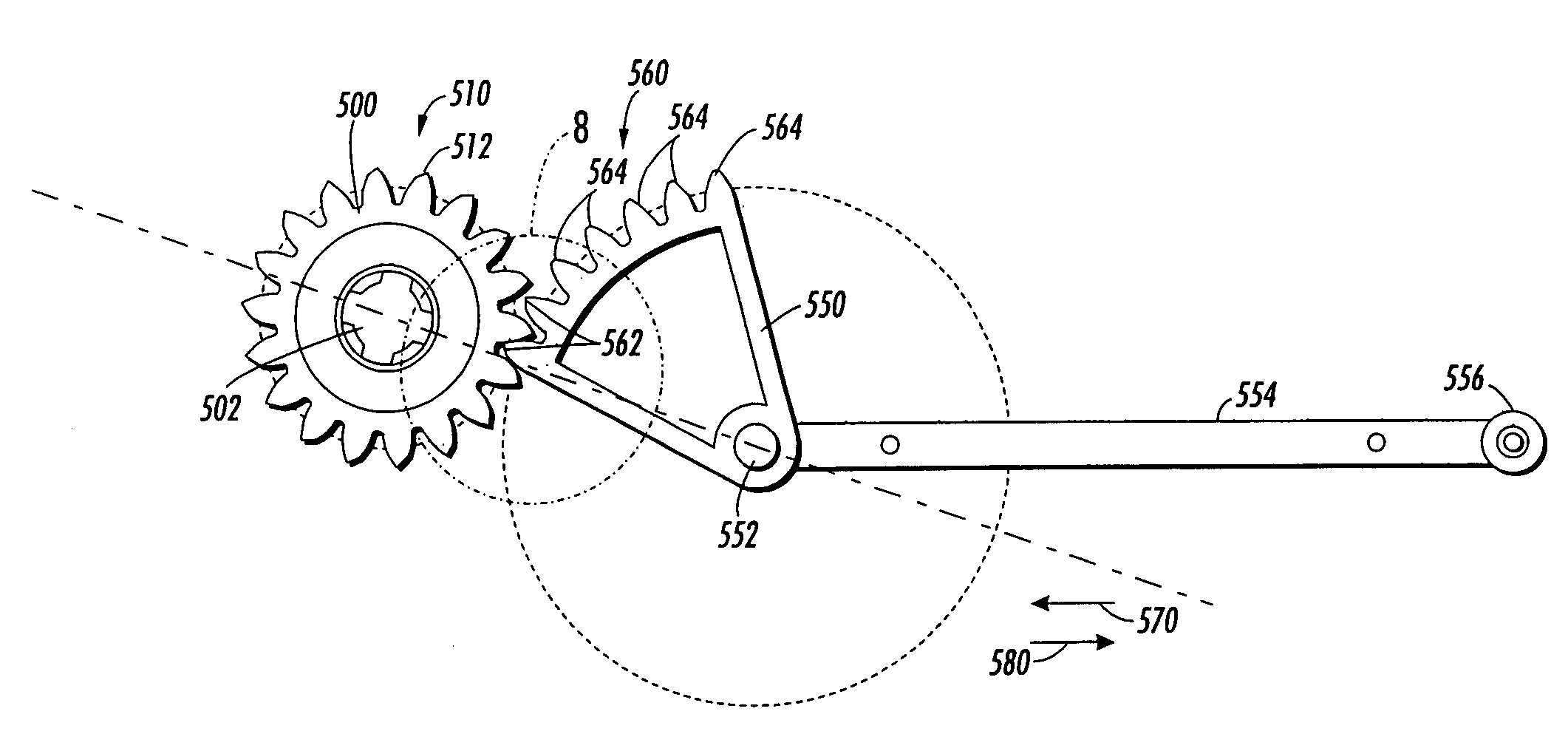
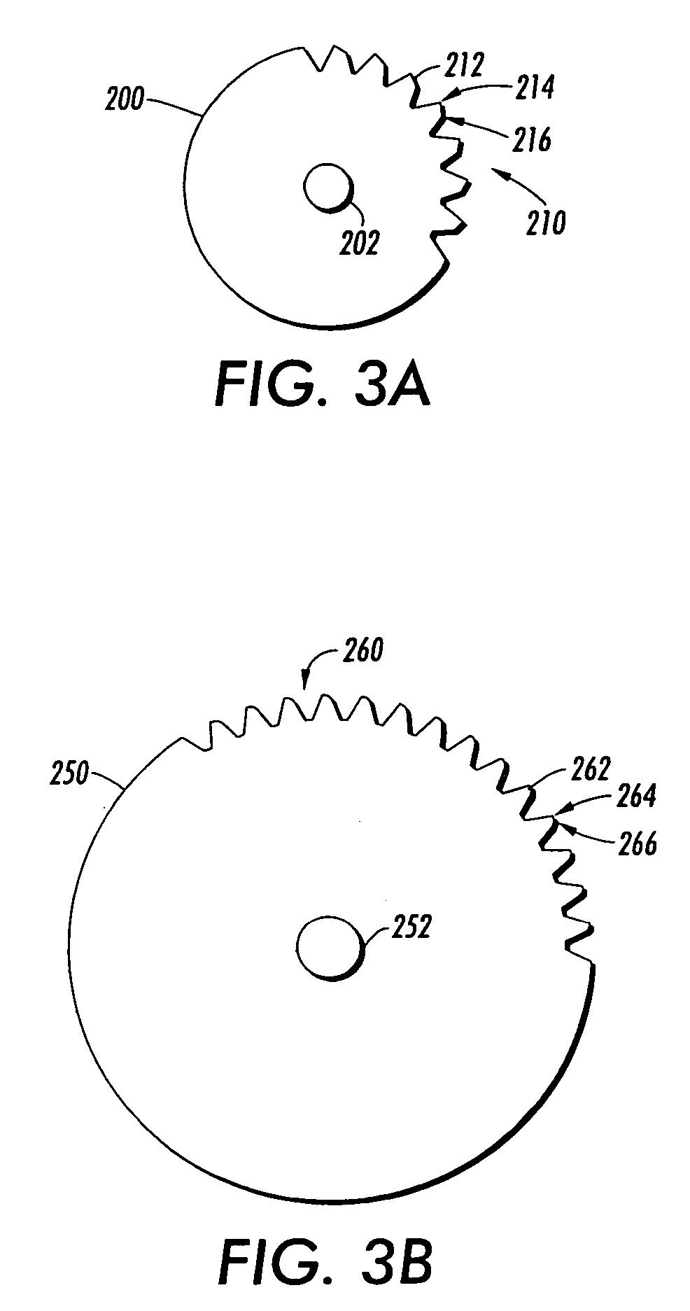
[0026]For a general understanding of two gears in accordance with the invention that can be incorporated into, for example, an image forming device, cars, appliances, or any structure currently available or later developed in which two gears are engaged or disengaged, reference is made to FIGS. 3-10, which depicts various embodiments of the invention.

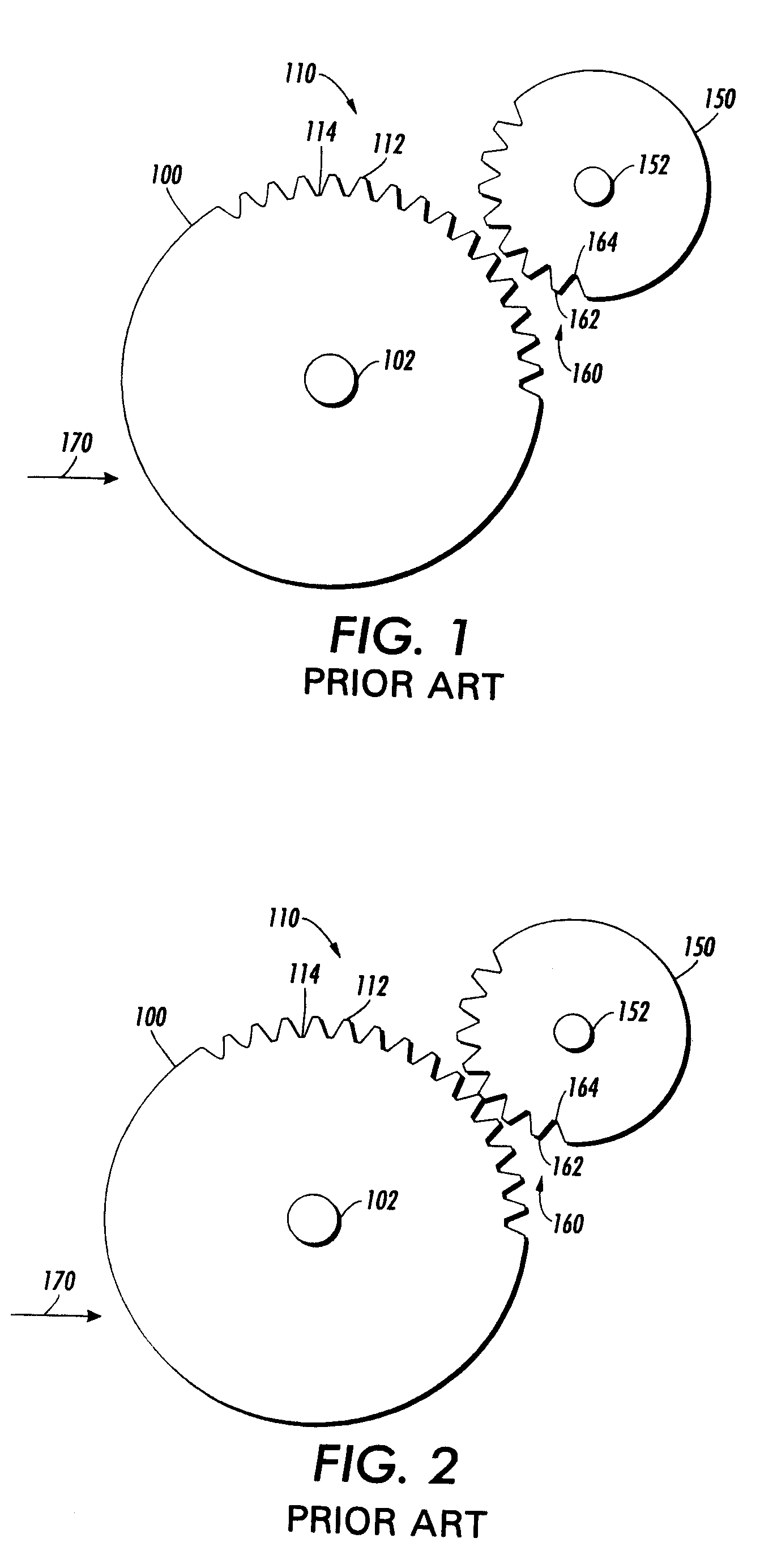
[0027]For clarification, FIGS. 1 and 2 illustrate two gears that engage and disengage in accordance with the conventional art. FIG. 1 illustrates two gears before engagement and FIG. 2 illustrates the two gears that are in tooth-to-tooth contact.

[0028]As shown in FIGS. 1 and 2, a first gear 100 and a second gear 150 are shown. The first gear 100 includes a center 102 and teeth 110 that surround a part of the outer circumference of the first gear 100. The teeth 110 include top lands 112 located at an outer surface of the teeth 110 of the first gear 100 that is farthest from the center 102 of the first gear 100 and bottom lands 114 locate...


PUM


Abstract

A gear and a method for combining a first gear with a second gear including the steps of moving the first gear relative to the second gear such that a first tooth of the first gear contacts a second tooth of the second gear, pressing the first tooth of the first gear against the second tooth of the second gear such that a resultant force is not directed to a center of at least one of the first gear or the second gear, wherein a torque is created by the resultant force, and rotating at least one of the first gear or the second gear based on the created torque until first teeth of the first gear mesh with second teeth of the second gear.

Description

BACKGROUND OF THE INVENTION[0001]1. Field of Invention[0002]The invention relates to systems and methods that enables direct engagement between two gears.[0003]2. Description of Related Art[0004]Two gears can be structured such that they can become engaged with or disengaged from each other. The two gears can also be structured such that they become engaged with or disengaged from each other (i.e., engage / disengage) once or a plurality of times. For example, the two gears can engage each other once and remain engaged. Alternatively, the two gears can repeatedly engage / disengage each other.[0005]When the two gears engage / disengage each other, a first gear of the two gears moves relative to a second gear of the two gears. When the two gears engage each other, teeth located along an outer circumference of the first gear are placed between teeth located along an outer circumference of the second gear. The rotation of the first gear thus affects the rotation of the second gear and vice v...

Claims


Application Information

Patent Timeline
Patent Type & Authority Patents(United States)
IPC IPC(8): F16H57/00F16H55/00F16H55/10F16H55/17
CPCF16H19/001F16H55/08F16H2019/008F16H2055/0866Y10T74/19619Y10T74/19884Y10T74/19972Y10T74/19358Y10T74/19949
Inventor JACOBS, JOS W.LOMBARDO, JOHN F.URBAN, CARL T.
Owner XEROX CORP
Why Eureka
Try Eureka