U-cover camera phone

a camera phone and lens cover technology, applied in the field of u-shaped lens phone cover, can solve the problem of low image quality of vga camera

Inactive Publication Date: 2009-09-01
MIRAMONTES IVAN
View PDF6 Cites 53 Cited by
  • Summary
  • Abstract
  • Description
  • Claims
  • Application Information

AI Technical Summary

Benefits of technology

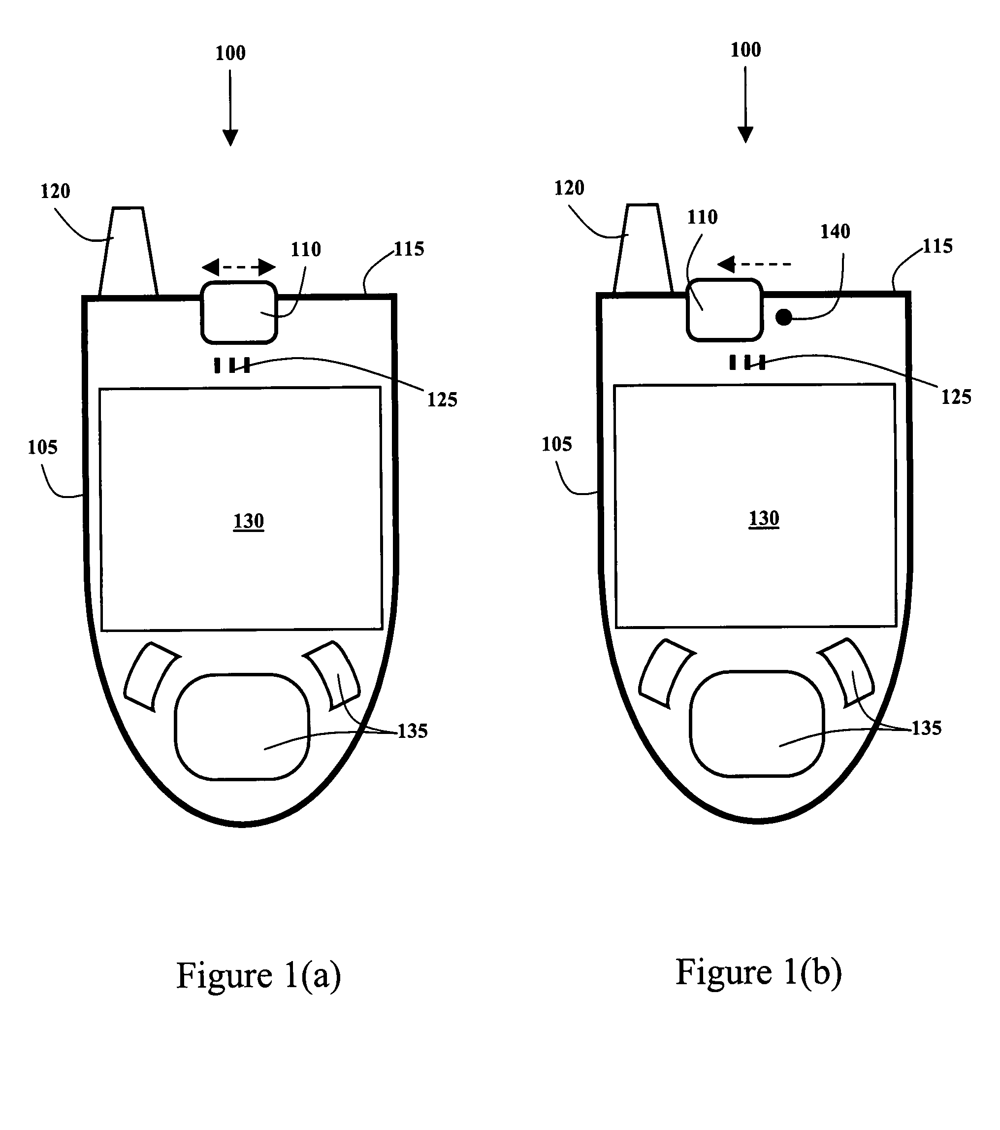
[0007]In the preferred embodiment, when the facing lens is exposed, the camera phone enters a telephone video conference mode, which activates the facing camera and dials a preset telephone conference number. The first camera lens is preferably adapted for taking low-resolution pictures and videos, and the away camera lens preferably includes a zoom feature and is adapted for taking high-resolution pictures and videos. The U-shaped lens cover is slide-ably attached to the exterior of the device body, making it very easy for the user to slide the cover from the closed position to the second or third positions. In an alternative embodiment, the U-shaped lens cover is housed within the interior of the device body and the sides of the lens cover slide into hollow spaces in the interior of the device body, when slid to the second or third positions. The device also preferably includes a re-useable flash that is permanently attached to the away side of the device body.
[0008]It is an object of the present invention to provide an easy-ON feature for an electrical device with a dual lens camera.
[0009]It is another object of the present invention to provide an active lens cover that is capable of protecting both lenses in a dual lens camera.
[0010]It is yet another object of the present invention to provide a smart camera phone that is capable of going from an OFF state to at least two different ON states simply by moving / opening the lens cover.

Problems solved by technology

The image quality of VGA cameras are low when compared to the image quality of conventional film cameras.
However, VGA camera are more than sufficient for use as a “user facing” camera.

Method used


Image

  • U-cover camera phone
  • U-cover camera phone
  • U-cover camera phone

Examples


embodiment 100

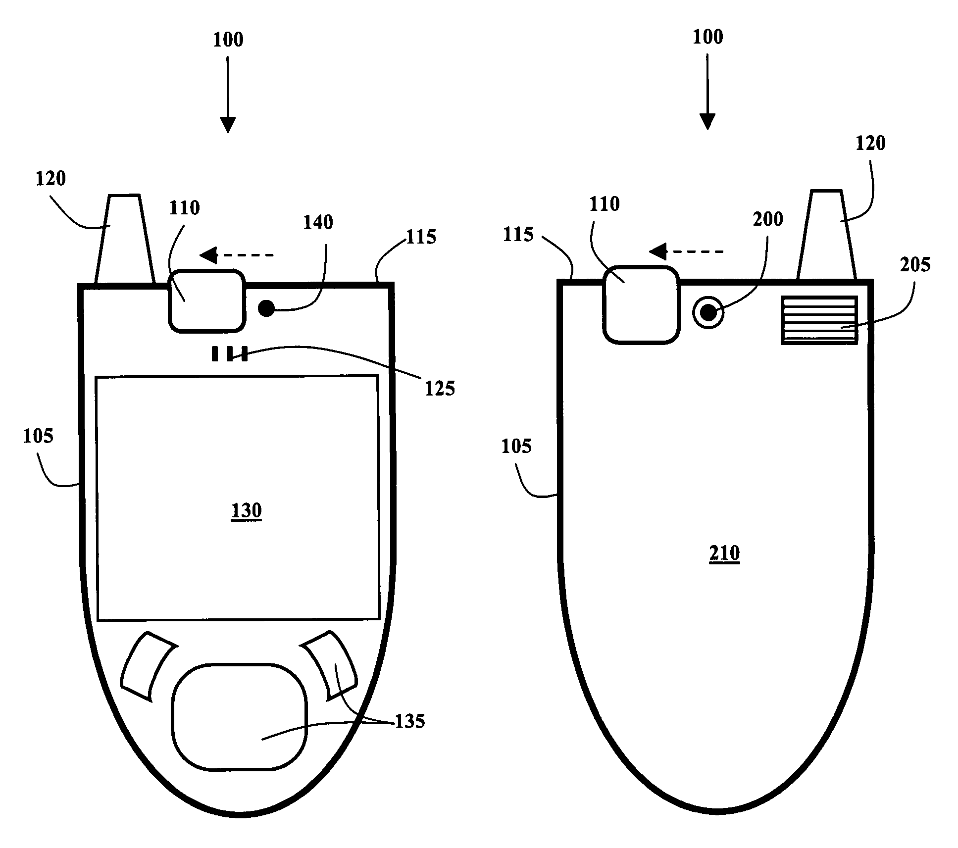
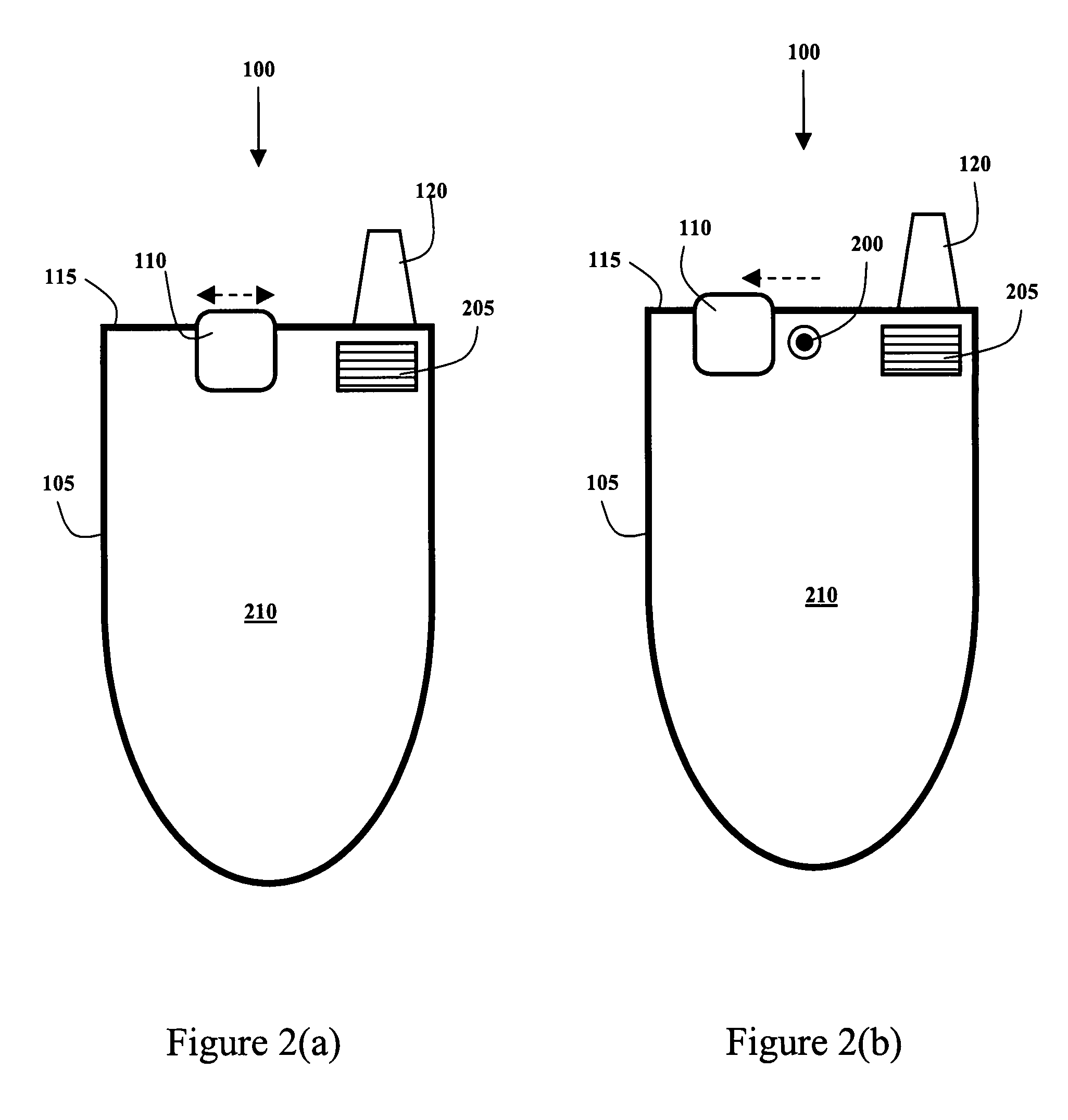
[0022]FIG. 2(a) shows the back 210 of the preferred embodiment 100 with the U-cover 110 in the first, or closed, position. The back 210 of the preferred smart phone includes a re-useable flash 205 that is permanently attached to the camera phone. The flash 205 is designed to work in conjunction with the second camera lens. The second camera lens is covered by the U-cover 110 when the cover 110 is in the first and second positions.

[0023]FIG. 2(b) shows the back 210 of the preferred embodiment 100 with the U-cover 110 in the third position, wherein the second digital camera lens 200, the “away camera”, is exposed. The second digital camera lens 200 is designed to operate with the same image capturing hardware in the camera phone as the first camera lens. Since, the second camera lens is capable of taking high-resolution pictures, the image capturing hardware preferably allows for the storage of more image information from the second camera. The second lens 200 faces away from the user...

embodiment 400

[0028]FIG. 4(b) shows the back 420 of the alternative embodiment 400 with the U-Cover 410 in the third position. When the U-Cover 410 is in the third position, the second, or away, camera lens 200 is exposed and may be used to take pictures and videos, depending on the desires of the user. The “away” lens 200 preferably includes zoom features, however other embodiments do not require a zoom feature. When the U-Cover 410 is in the second or third position, the cover slides into gaps in the device's body 405, just below the top 415 of the device. The U-Cover 410 of the alternative embodiment 400 is still an active, dual purpose, dual lens cover. When the electronic device 400 is powered OFF, the user can turn it ON simply by sliding the U-Cover 410 to the second or third position.

[0029]FIG. 5 shows steps in an exemplary method of operating the preferred embodiment. Initially, in step 500, the user is participating in a video telephone conference, wherein video information from the fac...


PUM


Abstract

An active lens cover for a device, such as a smart phone with a dual lens camera. The camera lens that faces the user and the camera lens that faces away from the user are not directly behind each other, but are slightly offset. The active lens cover is advantageously in the shape of a “U”, which allows a single cover to be used to protect both lenses. The offset arrangement of the two lenses allows the facing lens be exposed by sliding the lens cover in one direction, and the away lens to be exposed by sliding the lens cover in the opposite direction. When the lens cover is slid to expose the facing camera lens, the camera phone automatically turns ON and enters a pre-selected operating mode. When the cover is slid in the opposite direction to expose the away camera lens, the camera phone automatically turns ON and enters another pre-selected operating mode. The housing of the U-cover includes at least one sensor that tells the device's CPU what hardware to activate. In the preferred embodiment, the user is able to seamlessly switch between transmitting a video feed from either camera during a telephone call.

Description

[0001]The present invention was originally disclosed in U.S. provisional patent application Ser. No. 60 / 792,394 filed on Apr. 17, 2006, and priority is claimed to the provisional patent application. The present invention was also disclosed in USPTO Disclosure Document Number 609,862 filed on Dec. 6, 2006.BACKGROUND OF THE INVENTION[0002]The present invention relates generally to the field of cellular telephones and more specifically to a dual camera lens smart phone with a U-shaped lens cover.[0003]Cellular telephones have become an omnipresent device in society today. Manufacturers have added so many additional features to cellular telephones that it is easy to forget they also make telephone calls. Cellular telephones that double as an Internet browser, an MP3 player, a camera or a camcorder have recently acquired the name smart-phones. These smart-phones have benefited from continued miniature-rization of integrated circuits. Camera phones can now take high-resolution pictures an...

Claims


Application Information

Patent Timeline
Patent Type & Authority Patents(United States)
IPC IPC(8): H04N1/00G03B17/00
CPCH04M1/0264G03B17/00
Inventor MIRAMONTES, IVAN
Owner MIRAMONTES IVAN
Why Eureka
Try Eureka