Ion trap mass spectrometry

a mass spectrometer and ion trap technology, applied in mass spectrometers, separation processes, stability-of-path spectrometers, etc., can solve the problem of insufficient wide measurable mass range based on conventional ion traps, effective upper limit of trappable ions mass range, etc. problem, to achieve the effect of expanding a mass range and lowering the lmco valu

Inactive Publication Date: 2009-09-01
SHIMADZU CORP
View PDF3 Cites 46 Cited by
  • Summary
  • Abstract
  • Description
  • Claims
  • Application Information

AI Technical Summary

Benefits of technology

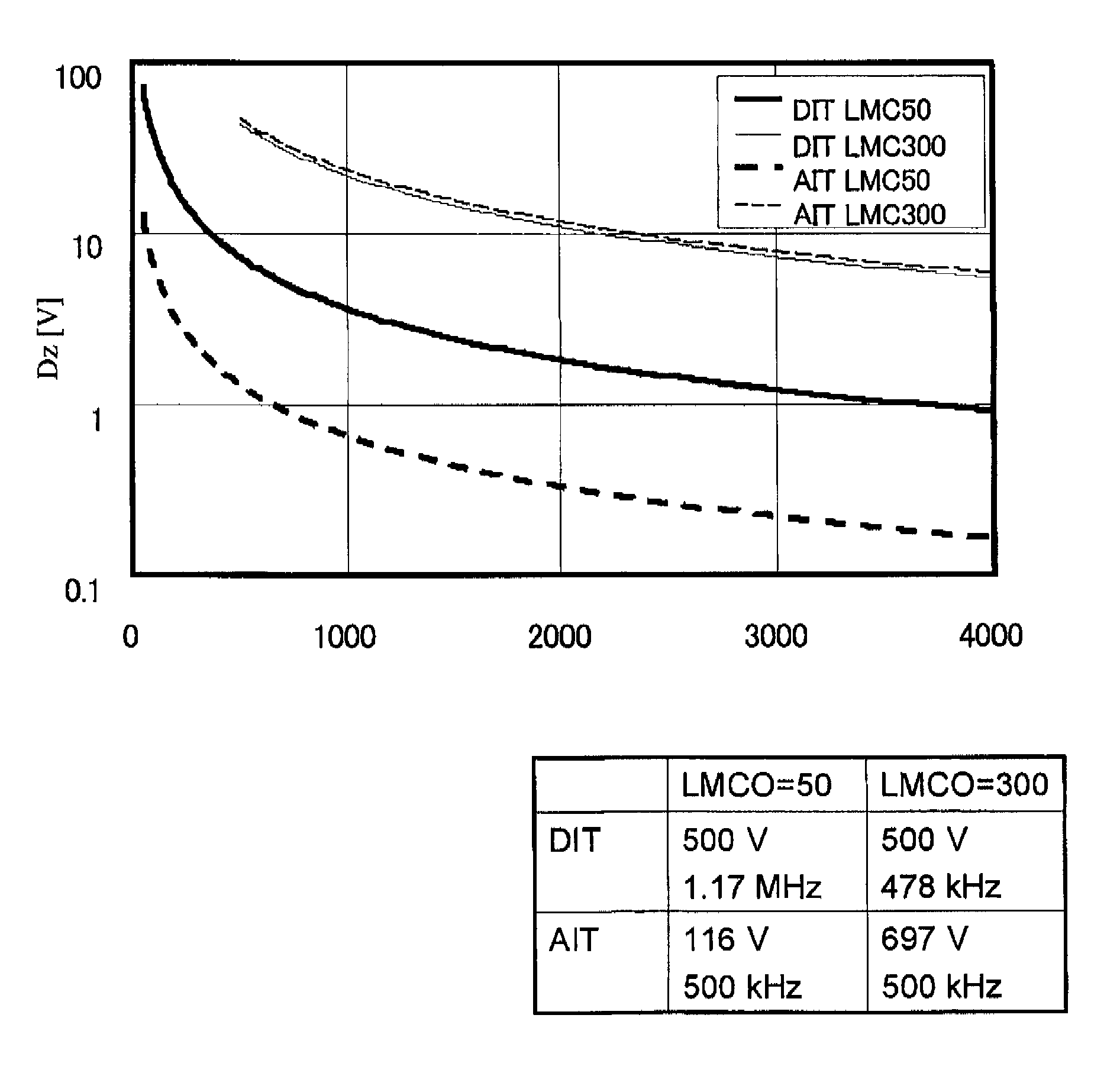
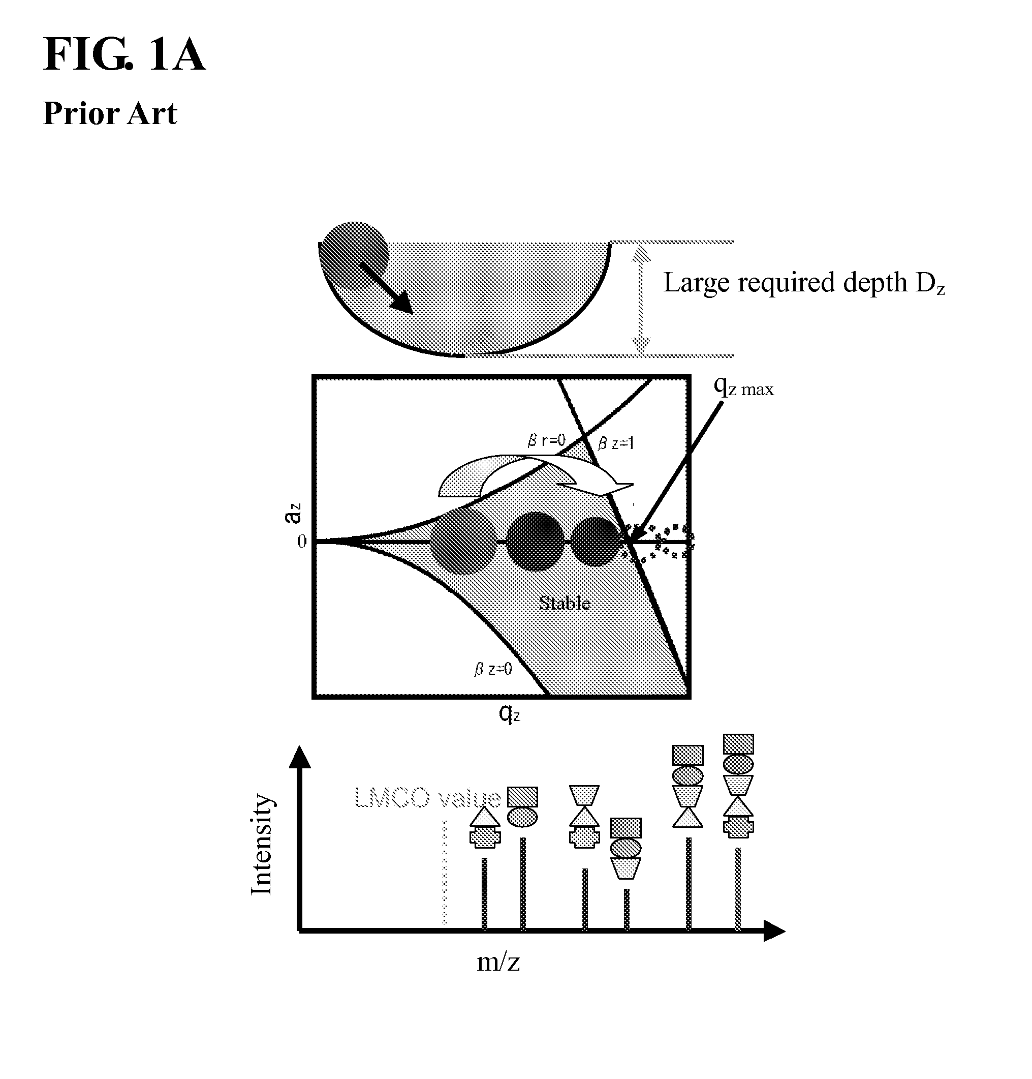
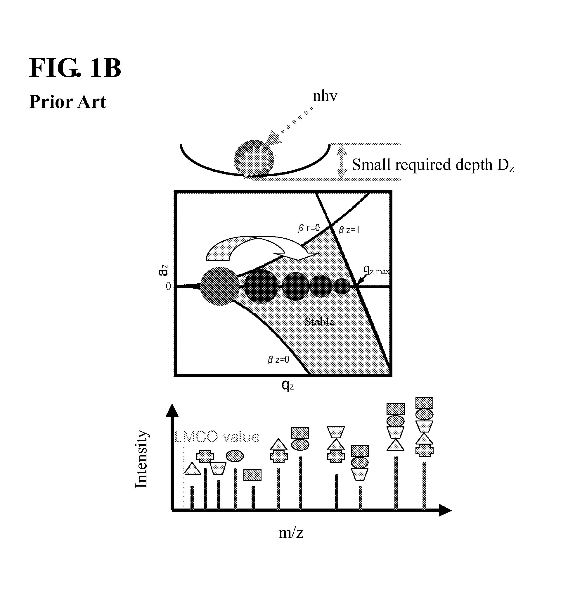
[0019]As above, in the present invention, under the condition that an amplitude of the ion-trapping RF voltage waveform is maintained at a constant value to keep a potential well depth at a relatively large value, a frequency of the ion-trapping RF voltage waveform is increased to lower the LMCO value (i.e., the ion trap section is configured as a frequency-driven ion trap). Thus, the potential well depth to be sensed by a precursor ion to be trapped under a lowed qz value can be kept at a relatively large value to allow a larger number of precursor ions to be trapped. Then, through irradiation with light, such as high-intensity infrared light, the precursor ions (i.e., molecular ions) in a trapped state are sufficiently cleaved, i.e., photodissociated, because the dissociation efficiency in the IRMPD process is not dependent on the potential well depth, as mentioned above. In addition, the potential well depth is also relatively large for fragment ions to be produced by photodissociation, and therefore a sufficient amount of fragment ions can be trapped. A combination of the frequency-driven ion trap and the IRMPD process makes it possible to perform a highly-sensitive MSn analysis and expand a mass range coverable in one cycle of the MSn analysis.

Problems solved by technology

This means that there is an effective upper limit on the mass range of trappable ions.
Although the IRMPD process theoretically has a wider mass range measurable at once as compared with the CID process, an actual measurable mass range based on conventional ion traps is not sufficiently wide in the existing circumstances.

Method used


Image

  • Ion trap mass spectrometry
  • Ion trap mass spectrometry
  • Ion trap mass spectrometry

Examples


Embodiment Construction

[0023]Exemplary embodiments of the present invention will now be described.

[0024]An ion trap mass spectrometer for MSn analysis, according to the exemplary embodiment of the present invention, fundamentally comprises an ion source section for generating sample ions, an ion trap section for trapping the sample ions generated by the ion source section, isolating (selecting) a precursor ion from the sample ions, and photodissociating the precursor ion in a trapped state into fragment ions, and an analyzer section for subjecting the fragment ions ejected from the ion trap section, to mass spectrometry so as to obtain information about a molecular structure of the precursor ion.

[0025]The ion trap mass spectrometer includes two types: one type adapted to sequentially eject respective ones of the fragment ions from the ion trap section while discriminating them on the basis of m / z value; and the other type adapted to eject all the fragment ions from the ion trap section at once and discrim...


PUM


Abstract

Disclosed is an ion trap mass spectrometer for MSn analysis, which comprises a frequency-driven ion trap section operable to trap sample ions and isolate a precursor ion from the sample ions, while setting an ion-trapping RF voltage waveform at a first frequency providing a first low-mass cutoff (LMCO) value, and, then after setting the ion-trapping RF voltage waveform at a second frequency greater than the first frequency to provide a second LMCO value less than the first LMCO value, without changing an amplitude of the ion-trapping RF voltage waveform, to irradiate the precursor ion in a trapped state with light so as to photodissociate the precursor ion into fragment ions; and an analyzer section operable to subject the fragment ions ejected from the ion trap section, to mass spectrometry so as to obtain information about a molecular structure of the precursor ion. The ion trap mass spectrometer of the present invention can maximize a mass range coverable in one cycle of MSn analysis.

Description

BACKGROUND OF THE INVENTION[0001]1. Field of the Invention[0002]The present invention relates to the field of mass spectrometry, and more particularly to an ion trap mass spectrometer and an ion trap mass spectrometric method designed to cover a wide mass range in one cycle of MSn analysis.[0003]2. Description of the Related Art[0004]First of all, a qz value of an ion trap in an ion trap mass spectrometer, a m / z (mass-to-charge ratio) value of a target ion to be trapped, and a potential well depth Dz to be sensed by a target ion, will be briefly described.[0005]The qz value of the ion trap is a parameter defined by the following Formula 1:[0006]qz=4⁢zVmr02⁢Ω2(1)[0007]wherein: z is an electronic charge of a target ion; V is an amplitude of RF applied to the ion trap; m is a mass of the target ion; r0 is an inscribed radius of the ring electrode of ion trap; and Ω is an angular frequency of the RF.[0008]According to a theoretical result in a stable region, the ion trap has a qz value ...

Claims


Application Information

Patent Timeline
Patent Type & Authority Patents(United States)
IPC IPC(8): H01J49/42H01J49/26
CPCH01J49/0059H01J49/427H01J49/424
Inventor FURUHASHI, OSAMUTAKESHITA, KENGOOGAWA, KIYOSHI
Owner SHIMADZU CORP
Why Eureka
Try Eureka