Method and apparatus for controlling fuel in a gas turbine engine

a gas turbine engine and fuel temperature technology, applied in the field of gas turbine engines, can solve the problems of engine not operating as efficiently and the temperature of the engine system is raised to unacceptable levels, and achieve the effect of facilitating the raising of the fuel heating valu

Inactive Publication Date: 2009-12-24
GENERAL ELECTRIC CO
View PDF31 Cites 58 Cited by
  • Summary
  • Abstract
  • Description
  • Claims
  • Application Information

AI Technical Summary

Benefits of technology

[0006]In another embodiment, a method of controlling fuel in a gas turbine engine including a fuel supply system channeling fuel to a combustor is provided. The method includes measuring a parameter relating to a lower heating value of a flow of fuel entering the combustor and controlling the parameter using waste heat from the engine to facilitate raising the lower heating value of the fuel.

Problems solved by technology

During engine operation, significant heat is produced which raises the temperature of engine systems to unacceptable levels.
With the heat exchangers generally sized for the highest engine operating temperature condition, at other more benign conditions, the fuel temperature is well below the maximum limit since the heat exchangers are not actively controlled and therefore the engine is not operating as efficiently as it could.

Method used


Image

  • Method and apparatus for controlling fuel in a gas turbine engine
  • Method and apparatus for controlling fuel in a gas turbine engine
  • Method and apparatus for controlling fuel in a gas turbine engine

Examples


Embodiment Construction

[0013]The following detailed description illustrates embodiments of the invention by way of example and not by way of limitation. It is contemplated that the invention has general application to machine temperature management in commercial, residential and industrial applications.

[0014]As used herein, an element or step recited in the singular and proceeded with the word “a” or “an” should be understood as not excluding plural elements or steps, unless such exclusion is explicitly recited. Furthermore, references to “one embodiment” of the present invention are not intended to be interpreted as excluding the existence of additional embodiments that also incorporate the recited features.

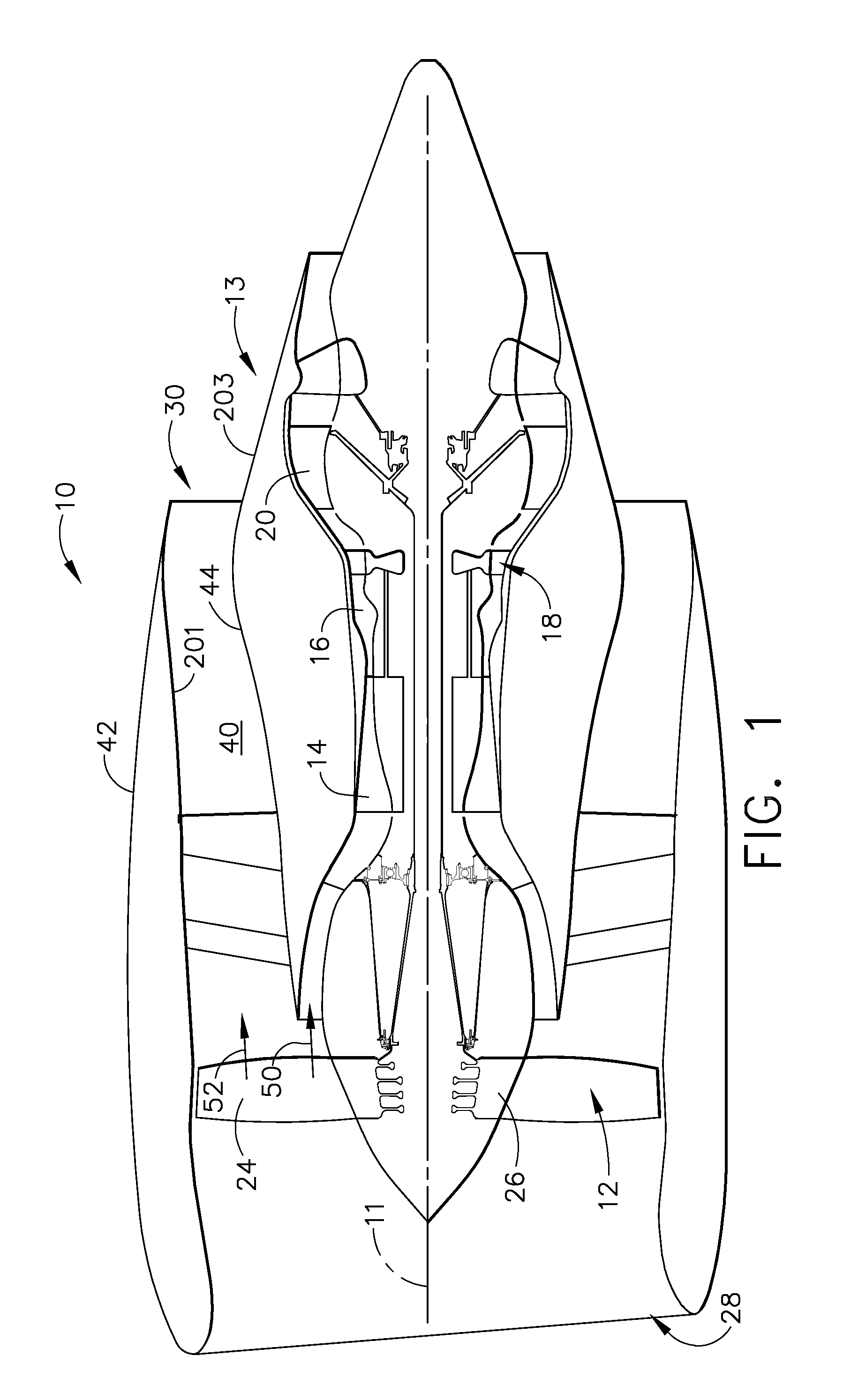
[0015]FIG. 1 is a schematic illustration of a gas turbine engine assembly 10 having a longitudinal axis 11 in accordance with an exemplary embodiment of the present invention. Gas turbine engine assembly 10 includes a fan assembly 12, and a core gas turbine engine 13. Core gas turbine engine includes ...


PUM


Abstract

A method and system for controlling fuel in a gas turbine engine including a fuel supply system channeling fuel to a combustor are provided. The system includes a first heat exchanger configured to transfer heat between a working fluid and a first cooling medium. The system also includes a second heat exchanger in series flow communication with the first heat exchanger wherein the second heat exchanger is configured to transfer heat between the working fluid and a second cooling medium. The system further includes a modulating valve configured to control the flow of at least one of the first and the second cooling media to maintain a temperature of the first or second cooling medium substantially equal to a predetermined limit.

Description

BACKGROUND OF THE INVENTION[0001]This invention relates generally to gas turbine engines, and more particularly, to methods and apparatus for controlling fuel in a gas turbine engine.[0002]Gas turbine engines typically include an inlet, a fan, low and high-pressure compressors, a combustor, and at least one turbine. The compressors compress air which is channeled to the combustor where it is mixed with fuel. The mixture is then ignited for generating hot combustion gases. The combustion gases are channeled to the turbine(s) which extracts energy from the combustion gases for powering the compressor(s), as well as producing useful work to propel an aircraft in flight or to power a load, such as an electrical generator.[0003]During engine operation, significant heat is produced which raises the temperature of engine systems to unacceptable levels. These systems must be cooled to improve their life and reliability. One example is the lubrication system that is utilized to facilitate lu...

Claims


Application Information

Patent Timeline
Patent Type & Authority Applications(United States)
IPC IPC(8): F02C9/26F02C7/224F02C7/14
CPCF01D25/18F02C7/14F02C7/16F02C7/18F05D2270/303F02C7/232F02C9/28Y02T50/675F02C7/224Y02T50/60
Inventor HUNTER, SCOTTDREIKOSEN, ANDREWMYERS, WILLIAM
Owner GENERAL ELECTRIC CO
Why Eureka
Try Eureka