Signal processing apparatus for an ultrasound transducer, ultrasound receiver and method for operating an ultrasound receiver

a technology of signal processing apparatus and ultrasound transducer, applied in the direction of response signal detection, transmission, diagnostics, etc., can solve the problems of high cost of power packs and insufficient shielding of power packs, and achieve the effect of further reducing signal interferen

Inactive Publication Date: 2009-09-08
BETRIEBSFORSCHUNGSINSTITUT VDEH INSTITUT FUR ANGEWANDTE FORSCHUNG
View PDF18 Cites 2 Cited by
  • Summary
  • Abstract
  • Description
  • Claims
  • Application Information

AI Technical Summary

Benefits of technology

[0009]As a result of the prompt digitalization of the analog signal produced by the ultrasound transducer, the further signal processing performed by the ultrasound receiver produces a digital output signal that is less susceptible to interference signals. Furthermore, prompt digitalization permits an increase of the useful signal range. While conventional systems generate signals of about 65 dB dynamic range, it is possible for systems in accordance with the present invention to use signals having a 120 dB (signal dynamic 1,000,000 / 1) dynamic range. The signal's dynamic range can be increased even further in the future by speeding up the clock frequency and improving the response of digital components in the electronic evaluation assembly. The dynamic range made possible by the invention allows a simplification of the system by the absence of a controllable preamplifier and the use of only a constant preamplifier, because only rough adjustment of the analog signal produced by the ultrasound transducer to the dynamic range of the analog-to-digital converter is sufficient. All the rest of the signal processing is digital. The use of a constant preamplifier allows also simplification or elimination of interference-prone components, in particular analog components, so that signal disturbances can be reduced even prior to the analog-to-digital converter.
[0010]The predominantly digital configuration of signal processing permits signal processing to be carried out with only a single power pack. The use of a single power pack is easy to shield without incurring high costs. Conventional analog signal processing units required various power packs to supply energy to the various components. As a consequence, the number of areas where interference can be introduced into the system increased, and the shielding for the numerous power packs incurred high costs so that oftentimes the power packs were not sufficiently shielded.
[0013]According to another feature of the present invention, the analog-to-digital converter has at least a 14-bit resolution and at least a 50 MHz clock frequency, preferably an 80 MHz clock frequency. Selection of an output and clock frequency requires an optimal compromise between equipment cost, which increases as the resolution increases, and the resolution. Increasing the resolution by one bit doubles the resolution of the converter, whereas a doubling of the clock frequency merely realizes an enhancement of √2. An increase of the resolution allows production of precise signals, even when the clock-frequency is lower, compared, for example, to an analog-to-digital converter having a resolution of 8 bit and a clock frequency of 500 Mhz, even though such analog-to-digital converters may certainly also be used in an ultrasound receiver according to the present invention.
[0023]According to another feature of the present invention, the ultrasound receiver may have a connection to a computer network, such as an internet. Suitably, the connection may be an Ethernet connection, preferably one using the TCP / IP protocol. Optical data transmission can be provided within the computer network, whereby the computer system is galvanically isolated from the ultrasound system, and signal interference is further reduced.
[0024]According to another feature of the present invention, the ultrasound receiver may be constructed to produce ultrasound signals which pass the ultrasound transducer in a same direction. This unidirectional testing prevents the ultrasound receiver from picking up erroneous signals, such as echo returns, in the opposite direction.
[0029]According to another feature of the present invention, the multiplier may be configured with adjustable multiplication factor, and / or may include a delay element with adjustable delay. An analyzer for monitoring the first and second digital signal may determine the multiplication factor and / or the delay to be adjusted. By adjusting the multiplication factor or the delay element, a lack of precision resulting from manufacturing variations in the construction of the ultrasound transducer can be compensated, for example in the separation of the two ultrasound transducers from the surface of the tested material, or in the pickup sensitivity of the respective ultrasound transducer. In particular, the analyzer can determine the delay being adjusted based on the relative position of the zero passages of the first and second digital signals with respect to each other. Normally, the delay is t / 4, when the ultrasound transmitters are offset by a quarter wavelength (λ / 4).

Problems solved by technology

As a consequence, the number of areas where interference can be introduced into the system increased, and the shielding for the numerous power packs incurred high costs so that oftentimes the power packs were not sufficiently shielded.

Method used


Image

  • Signal processing apparatus for an ultrasound transducer, ultrasound receiver and method for operating an ultrasound receiver
  • Signal processing apparatus for an ultrasound transducer, ultrasound receiver and method for operating an ultrasound receiver
  • Signal processing apparatus for an ultrasound transducer, ultrasound receiver and method for operating an ultrasound receiver

Examples


Embodiment Construction

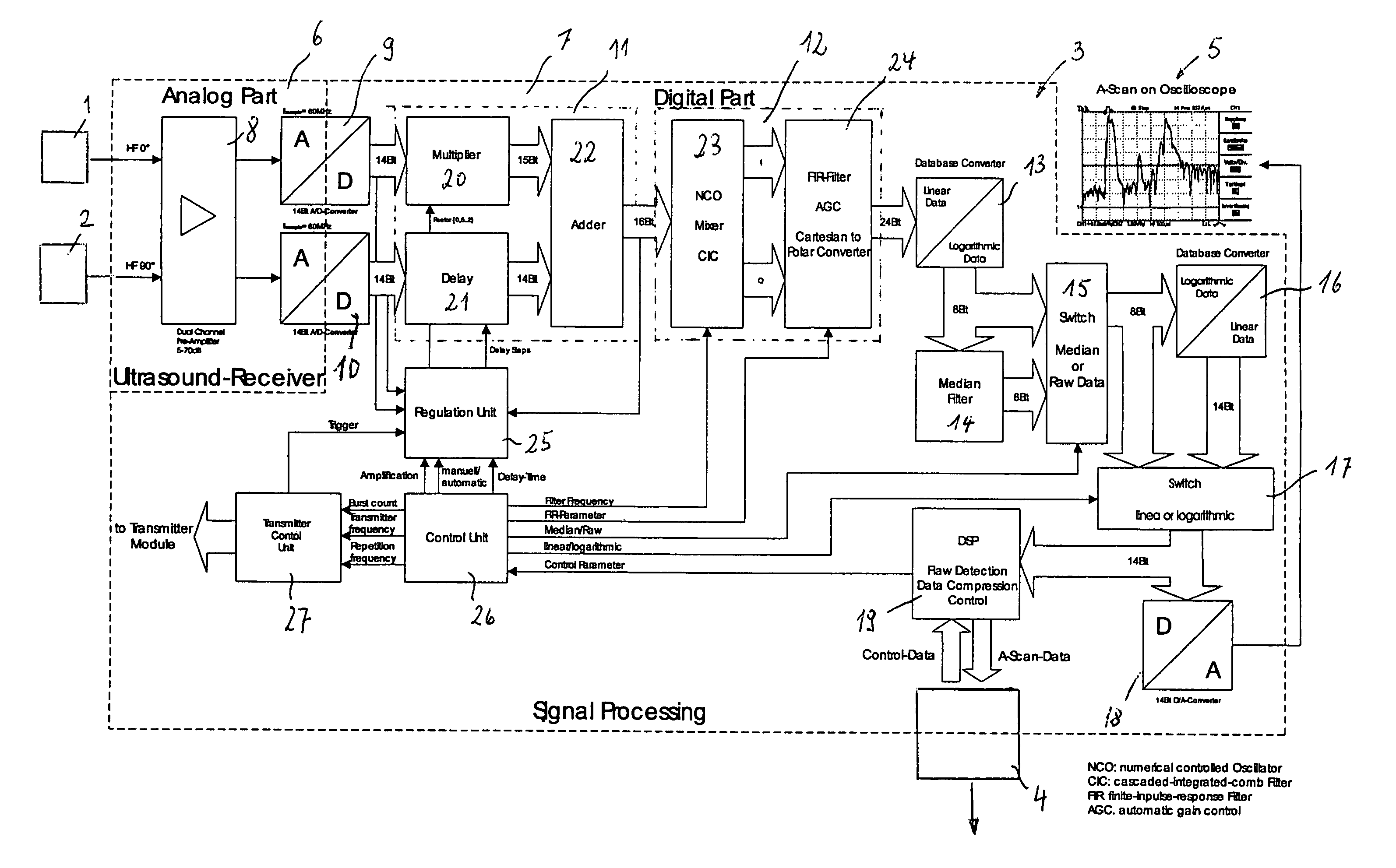
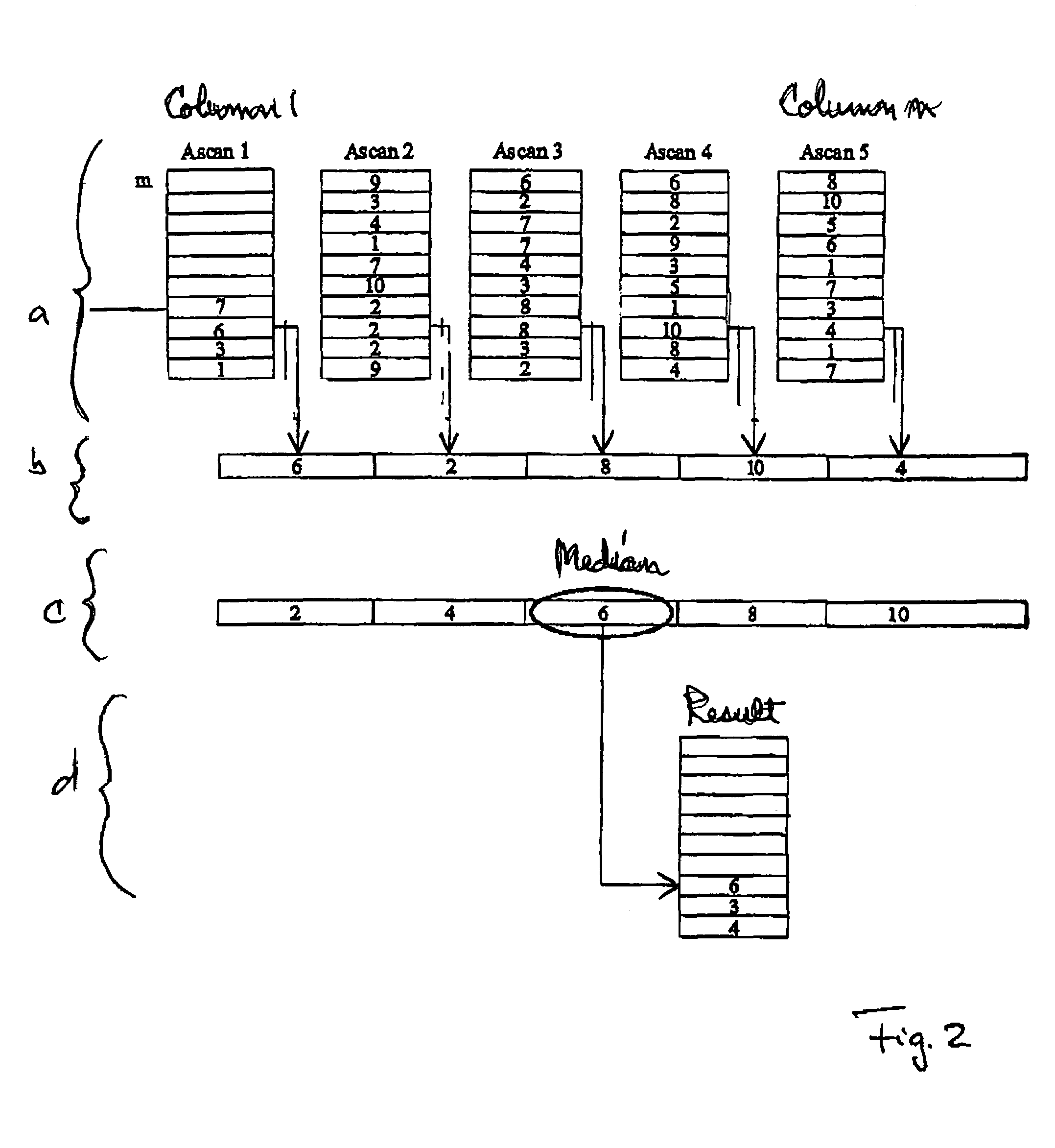
[0037]Throughout all the Figures, same or corresponding elements are generally indicated by same reference numerals. These depicted embodiments are to be understood as illustrative of the invention and not as limiting in any way. It should also be understood that the drawings are not necessarily to scale and that the embodiments are sometimes illustrated by graphic symbols, phantom lines, diagrammatic representations and fragmentary views. In certain instances, details which are not necessary for an understanding of the present invention or which render other details difficult to perceive may have been omitted.

[0038]Turning now to the drawing, and in particular to FIG. 1, there is shown a block diagram of a signal receiver in accordance with the present invention, depicting an ultrasound receiver having two ultrasound transducers 1, 2, and a signal processing unit 3 connected to the ultrasound transducers 1, 2. The output of the signal processing apparatus 3 is an Ethernet connectio...


PUM


Abstract

To reduce signal interference and improve the signal-to-noise ratio in the transmitted signal, the analog signals produced by an ultrasound transducer are promptly digitized. In accordance with the invention, the demodulator is already shielded from the ultrasound transducers, immediately after the preamplifier, which is itself shielded from the ultrasound transducers, by an analog to digital converter, for example.

Description

CROSS-REFERENCES TO RELATED APPLICATIONS[0001]This application claims the priority of German Patent Application, Serial No. 10 2004 035 950.4, filed Jul. 23, 2004, pursuant to 35 U.S.C. 119(a)-(d), the subject matter of which is / are incorporated herein by reference.BACKGROUND OF THE INVENTION[0002]The present invention pertains to a signal processing apparatus for ultrasound transducers, and to an ultrasound receiver apparatus. More particularly, the present invention directed to improving the signal received by such apparatus.[0003]Ultrasound receiver may be used, for example, for non-destructive materials testing of tubes, wires or belts, by generating an ultrasound wave in the test object, e.g. by means of a piezo-electric test head or, for non-contact applications, by means of an electromagnetic acoustic transducer (EMAT). The emitted ultrasound signal is then picked up by the ultrasound receiver and converted into an output signal. Information about flaws in the material of the...

Claims


Application Information

Patent Timeline
Patent Type & Authority Patents(United States)
IPC IPC(8): A61B8/00
CPCG01N29/2412H04B11/00H03D3/007G01N29/36
Inventor OBERHOFF, DIETMARFLOHR, GUIDOCOEN, GUNTHER
Owner BETRIEBSFORSCHUNGSINSTITUT VDEH INSTITUT FUR ANGEWANDTE FORSCHUNG
Why Eureka
Try Eureka