Signal processing apparatus for an ultrasound transducer, ultrasound receiver and method for operating an ultrasound receiver

a technology of signal processing apparatus and ultrasound transducer, applied in the direction of response signal detection, transmission, diagnostics, etc., can solve the problems of high cost of power packs and insufficient shielding of power packs, and achieve the effect of further reducing signal interferen

Inactive Publication Date: 2006-02-16
BETRIEBSFORSCHUNGSINSTITUT VDEH INSTITUT FUR ANGEWANDTE FORSCHUNG
View PDF13 Cites 13 Cited by
  • Summary
  • Abstract
  • Description
  • Claims
  • Application Information

AI Technical Summary

Benefits of technology

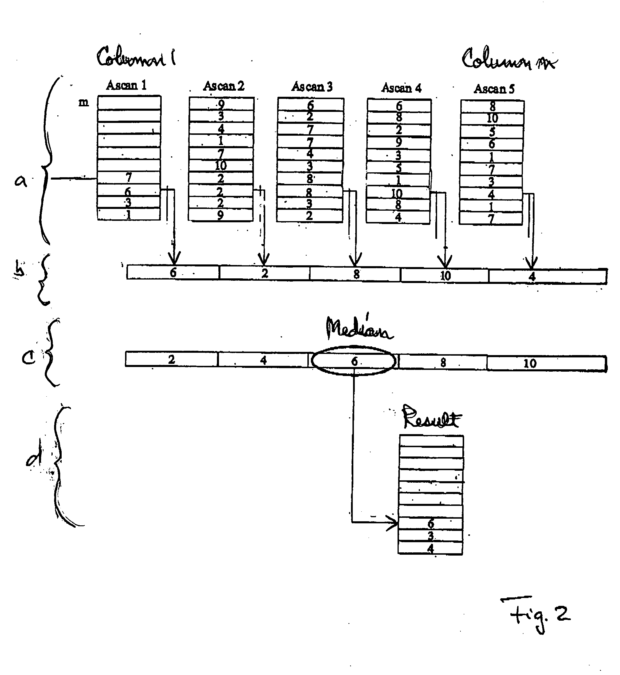
[0022] The ultrasound transducer may include a switched bypass for the median filter so that the signals can be processed without using the median filter. For example, this permits the action and effectiveness of the median filter to be analyzed.
[0023] According to another feature of the present invention, the ultrasound receiver may have a connection to a computer network, such as an internet. Suitably, the connection may be an Ethernet connection, preferably one using the TCP/IP protocol. Optical data trans

Problems solved by technology

As a consequence, the number of areas where interference can be introduced into the system increased, and the shieldi

Method used


Image

  • Signal processing apparatus for an ultrasound transducer, ultrasound receiver and method for operating an ultrasound receiver
  • Signal processing apparatus for an ultrasound transducer, ultrasound receiver and method for operating an ultrasound receiver
  • Signal processing apparatus for an ultrasound transducer, ultrasound receiver and method for operating an ultrasound receiver

Examples


Embodiment Construction

[0037] Throughout all the Figures, same or corresponding elements are generally indicated by same reference numerals. These depicted embodiments are to be understood as illustrative of the invention and not as limiting in any way. It should also be understood that the drawings are not necessarily to scale and that the embodiments are sometimes illustrated by graphic symbols, phantom lines, diagrammatic representations and fragmentary views. In certain instances, details which are not necessary for an understanding of the present invention or which render other details difficult to perceive may have been omitted.

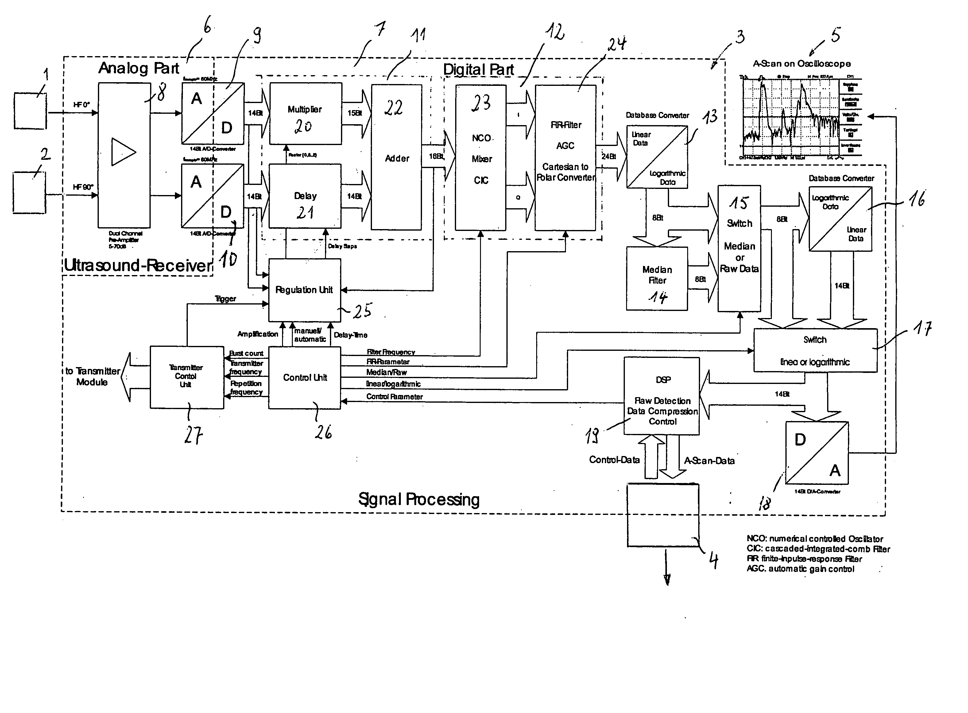
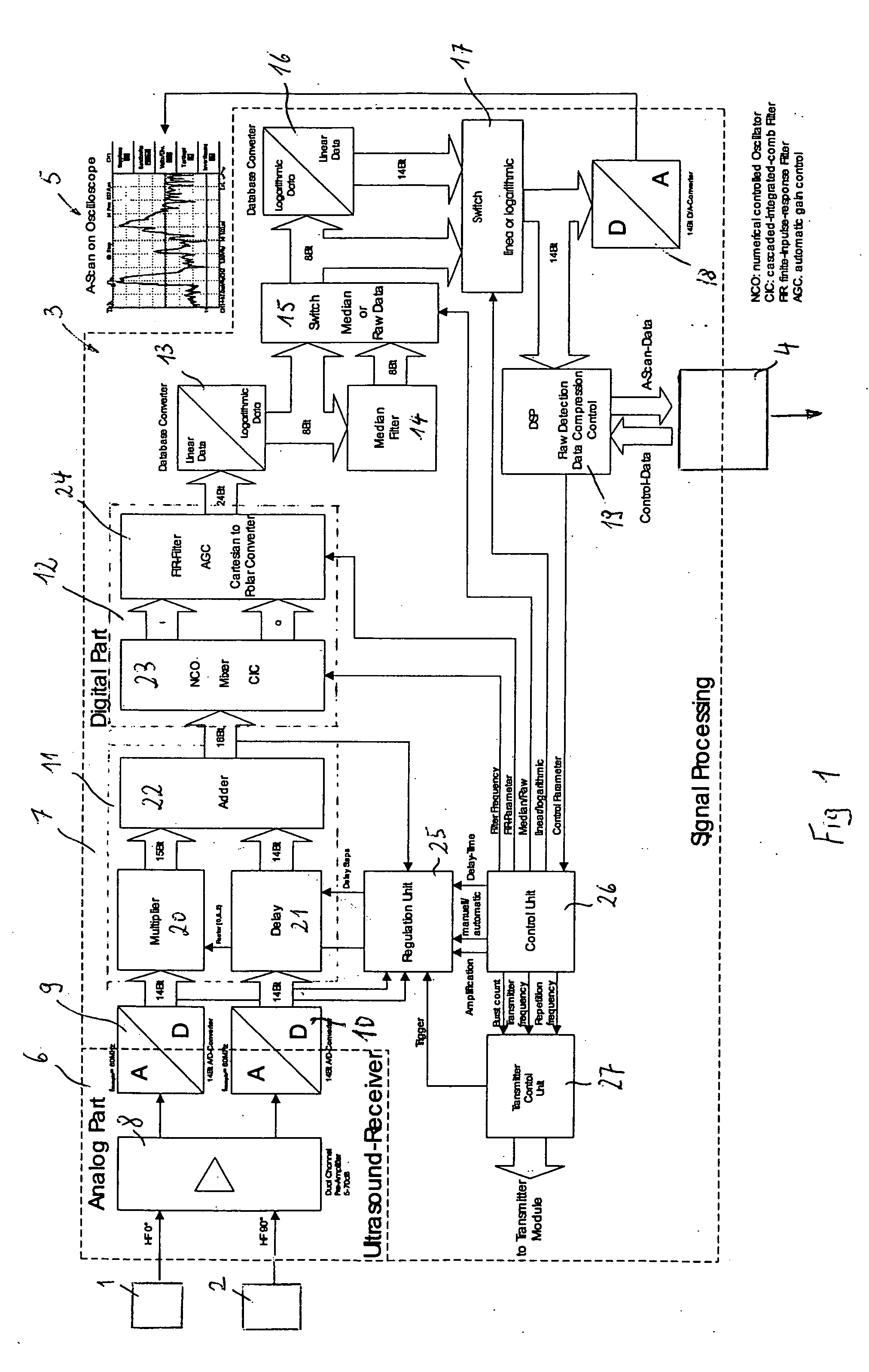
[0038] Turning now to the drawing, and in particular to FIG. 1, there is shown a block diagram of a signal receiver in accordance with the present invention, depicting an ultrasound receiver having two ultrasound transducers 1, 2, and a signal processing unit 3 connected to the ultrasound transducers 1, 2. The output of the signal processing apparatus 3 is an Ethernet connec...


PUM


Abstract

To reduce signal interference and improve the signal-to-noise ratio in the transmitted signal, the analog signals produced by an ultrasound transducer are promptly digitized. In accordance with the invention, the demodulator is already shielded from the ultrasound transducers, immediately after the preamplifier, which is itself shielded from the ultrasound transducers, by an analog to digital converter, for example.

Description

CROSS-REFERENCES TO RELATED APPLICATIONS [0001] This application claims the priority of German Patent Application, Serial No. 10 2004 035 950.4, filed Jul. 23, 2004, pursuant to 35 U.S.C. 119(a)-(d), the subject matter of which is / are incorporated herein by reference. BACKGROUND OF THE INVENTION [0002] The present invention pertains to a signal processing apparatus for ultrasound transducers, and to an ultrasound receiver apparatus. More particularly, the present invention directed to improving the signal received by such apparatus. [0003] Ultrasound receiver may be used, for example, for non-destructive materials testing of tubes, wires or belts, by generating an ultrasound wave in the test object, e.g. by means of a piezo-electric test head or, for non-contact applications, by means of an electromagnetic acoustic transducer (EMAT). The emitted ultrasound signal is then picked up by the ultrasound receiver and converted into an output signal. Information about flaws in the material...

Claims


Application Information

Patent Timeline
IPC IPC(8): A61B8/00
CPCG01N29/2412H04B11/00H03D3/007G01N29/36
Inventor OBERHOFF, DIETMARFLOHR, GUIDOCOEN, GUNTHER
Owner BETRIEBSFORSCHUNGSINSTITUT VDEH INSTITUT FUR ANGEWANDTE FORSCHUNG
Why Eureka
Try Eureka