Oil pump rotor assembly

a technology of oil pump and rotor, which is applied in the direction of rotary/oscillating piston pump components, machines/engines, liquid fuel engines, etc., to achieve the effect of excellent silence properties and noise can be surely prevented from being generated

Inactive Publication Date: 2009-09-15
DIAMET CORP
View PDF7 Cites 2 Cited by
  • Summary
  • Abstract
  • Description
  • Claims
  • Application Information

AI Technical Summary

Benefits of technology

[0017]The present invention has been made in consideration of the above circumstances. It is therefore an object of the present invention to appropriately set the tooth profile of an inner rotor and the tooth profile of an outer rotor, and appropriately set clearances between the inner and outer rotors, so that, even when the hydraulic pressure generated in the oil pump rotor assembly is extremely small and the torque that drives the oil pump rotor assembly changes, noise can be surely prevented from being generated.
[0025]According to this invention, the side clearance between the tooth surfaces of the inner and outer rotors is made small compared with the conventional oil pump rotor assembly while the tip clearance between the external teeth of the inner rotor and the internal teeth of the outer rotor is surely obtained. Thus, it is possible to realize an oil pump rotor assembly with a small play between the inner and outer rotors and an excellent silence property. Particularly, even if the hydraulic pressure generated in the oil pump rotor assembly is extremely small, and the torque that drives the oil pump rotor assembly changes, the internal teeth of the outer rotor can be prevented from colliding with the external teeth of the inner rotor. Thus, the silence property of the oil pump rotor assembly can be surely improved.
[0027]According to this invention, the inner and outer rotors are constructed to satisfy the following inequality:0.005 mm≦(φDo+φdo)−(φDi+φdi)As a result, the size of backlash can be adequately maintained while the tip clearance can be surely obtained, and noise due to the engagement between the inner and outer rotors can be reduced. Further, the inner and outer rotors are constructed to satisfy the following inequality:(φDo+φdo)−(φDi+φdi)≦0.070 mmAs a result, the mechanical efficiency can be prevented from being reduced and noise can be prevented from being generated.
[0028]According to the oil pump rotor related to the present invention, clearances between the external teeth of the inner rotor and the internal teeth of the outer rotor are surely obtained and the side clearance between tooth surfaces of the inner and outer rotors is made small compared with the conventional oil pump rotor assembly. Thus, it is possible to realize an oil pump rotor assembly with a small play between the inner and outer rotors and an excellent silence property. Particularly, even when the hydraulic pressure generated in the oil pump rotor assembly is extremely small and the torque that drives the oil pump rotor assembly changes, noise can be surely prevented from being generated.

Problems solved by technology

That is, in a case that the hydraulic pressure generated in the oil pump rotor assembly is extremely small, and the torque that drives the oil pump rotor assembly changes, the internal teeth of the outer rotor and the external teeth of the inner rotor collide with each other.

Method used


Image

  • Oil pump rotor assembly
  • Oil pump rotor assembly
  • Oil pump rotor assembly

Examples


Embodiment Construction

[0050]One embodiment of an oil pump rotor assembly according to the present invention will now be described with reference to FIGS. 1 through 4.

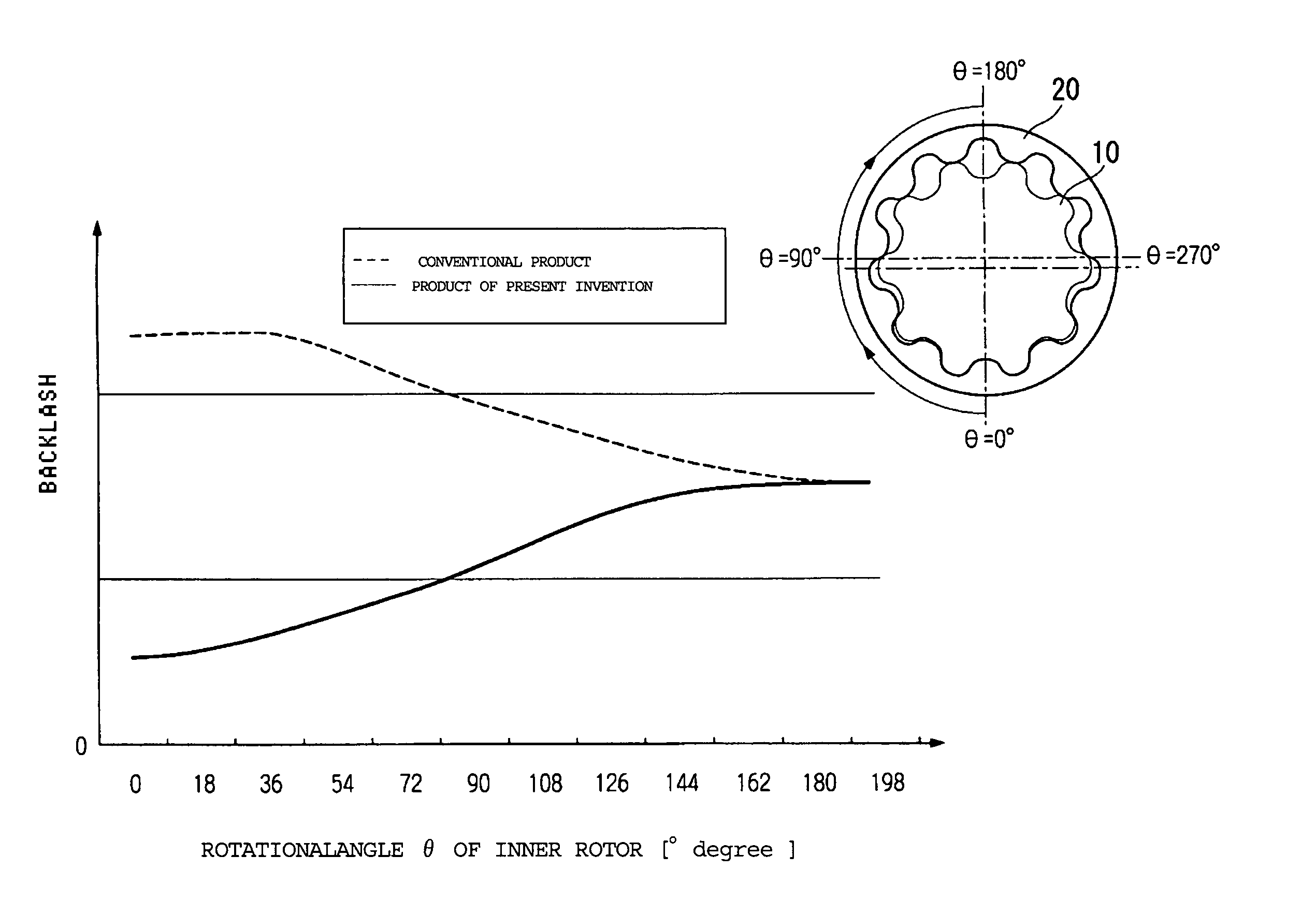
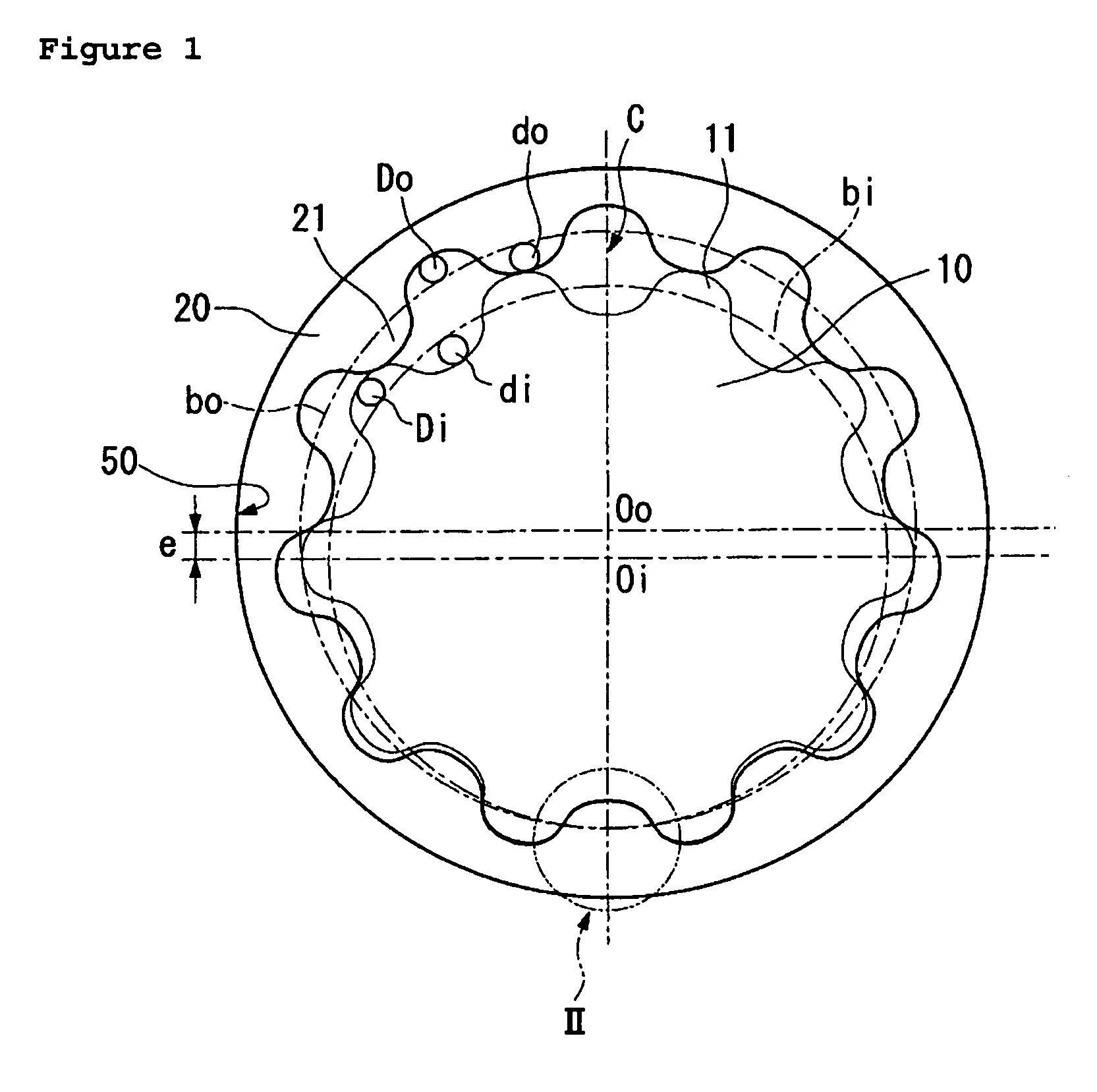
[0051]The oil pump shown in FIG. 1 comprises an inner rotor 10 formed with “n” external teeth (“n” is a natural number, and n=10 in this embodiment), an outer rotor 20 formed with “n+1” internal teeth (n+1=11 in this embodiment) which are engageable with the external teeth, and a casing 50 which accommodates the inner rotor 10 and the outer rotor 20.

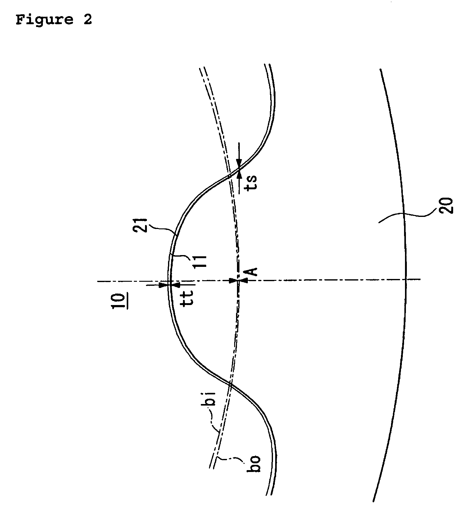
[0052]Between the tooth surfaces of the inner and outer rotors 10 and 20, there are formed plural cells C in the direction of rotation of the inner and outer rotors 10 and 20. Each of the cells C is delimited at a front portion and at a rear portion as viewed in the direction of rotation of the inner and outer rotors 10 and 20 by contact between the external teeth 11 of the inner rotor 10 and the internal teeth 21 of the outer rotor 20, and is also delimited at either side portions by the casing ...


PUM


Abstract

An oil pump rotor assembly is disclosed. An inner rotor formed with n external teeth is based on cycloid curves which are generated by a first circumscribed-rolling circle and a first inscribed-rolling circle by rolling the first circumscribed-rolling circle and first inscribed-rolling circle along an inner base circle. An outer rotor formed with n+1 internal teeth (n+1 is the number of teeth) is based on cycloid curves which are generated by a second circumscribed-rolling circle and a second inscribed-rolling circle by rolling the second circumscribed-rolling circle and second inscribed-rolling circles along an outer base circle.

Description

CROSS-REFERENCE TO PRIOR APPLICATION[0001]This is a U.S. national phase application under 35 U.S.C. §371 of International Patent Application No. PCT / JP2004 / 012170 filed Aug. 25, 2004 and claims the benefit of Japanese Patent Application No. 2003-309348 filed Sep. 1, 2003, both of which are incorporated by reference herein. The International Application was published in Japanese on Mar. 10, 2005 as WO 2004 / 021969 A1 under PCT Article 21(2).TECHNICAL FIELD[0002]This invention relates to an oil pump rotor assembly used in an oil pump which draws and discharges fluid by volume change of cells formed between an inner rotor and an outer rotor.BACKGROUND ART[0003]A conventional oil pump comprises an inner rotor formed with “n” external teeth (“n” is a natural number), an outer rotor formed with “n+1” internal teeth which are engageable with the external teeth, and a casing in which a suction port for drawing fluid and a discharge port for discharging fluid are formed. The inner rotor is ro...

Claims


Application Information

Patent Timeline
Patent Type & Authority Patents(United States)
IPC IPC(8): F04C2/00F03C2/00F04CF04C2/10F04C2/08F04C15/00
CPCF04C2/084F04C2/102F04C2/10
Inventor HOSONO, KATSUAKI
Owner DIAMET CORP
Why Eureka
Try Eureka