MEMS based motor starter with motor failure detection

a technology of microelectromechanical system and motor, applied in the direction of motor/generator/converter stopper, dynamo-electric converter control, instruments, etc., can solve the problems of undesirable safety issues, costly monitoring by skilled technicians, and inability to integrate control circuitry or logic controls into the conventional motor starter, etc., to facilitate the control of electrical current passing.

Active Publication Date: 2009-09-15
ABB (SCHWEIZ) AG
View PDF55 Cites 21 Cited by
  • Summary
  • Abstract
  • Description
  • Claims
  • Application Information

AI Technical Summary

Problems solved by technology

With regards to early warning motor protection, previously conceived solutions involved costly monitoring of motors by skilled technicians and / or providing complex motor monitoring equipment alongside already bulky motor starters.
However, conventional motor starters lack control circuitry or logical controls integrated thereon.
Therefore, monitoring by skilled technicians may include costly downtime of motor starter equipment and undesirable safety issues.
Therefore, conventional approaches to early warning motor protection have many drawbacks.
Unfortunately, contactors such as vacuum contactors do not lend themselves to easy visual inspection as the contactor tips are encapsulated in a sealed, evacuated enclosure.
Further, while the vacuum contactors are well suited for handling the switching of large motors, transformers and capacitors, they are known to cause undesirable transient overvoltages, particularly when the load is switched off.
Such zero crossing prediction is prone to error as many transients may occur in this prediction time interval.
However, since solid-state switches do not create a physical gap between contacts when they are switched into a non-conducing state, they experience leakage current.
Furthermore, due to internal resistances, when solid-state switches operate in a conducting state, they experience a voltage drop.
Both the voltage drop and leakage current contribute to the generation of excess neat under normal operating circumstances, which may affect switch performance and life.
Moreover, due at least in part to the inherent leakage current associated with solid-state switches, their use in circuit breaker applications is not practical.

Method used


Image

  • MEMS based motor starter with motor failure detection
  • MEMS based motor starter with motor failure detection
  • MEMS based motor starter with motor failure detection

Examples


Embodiment Construction

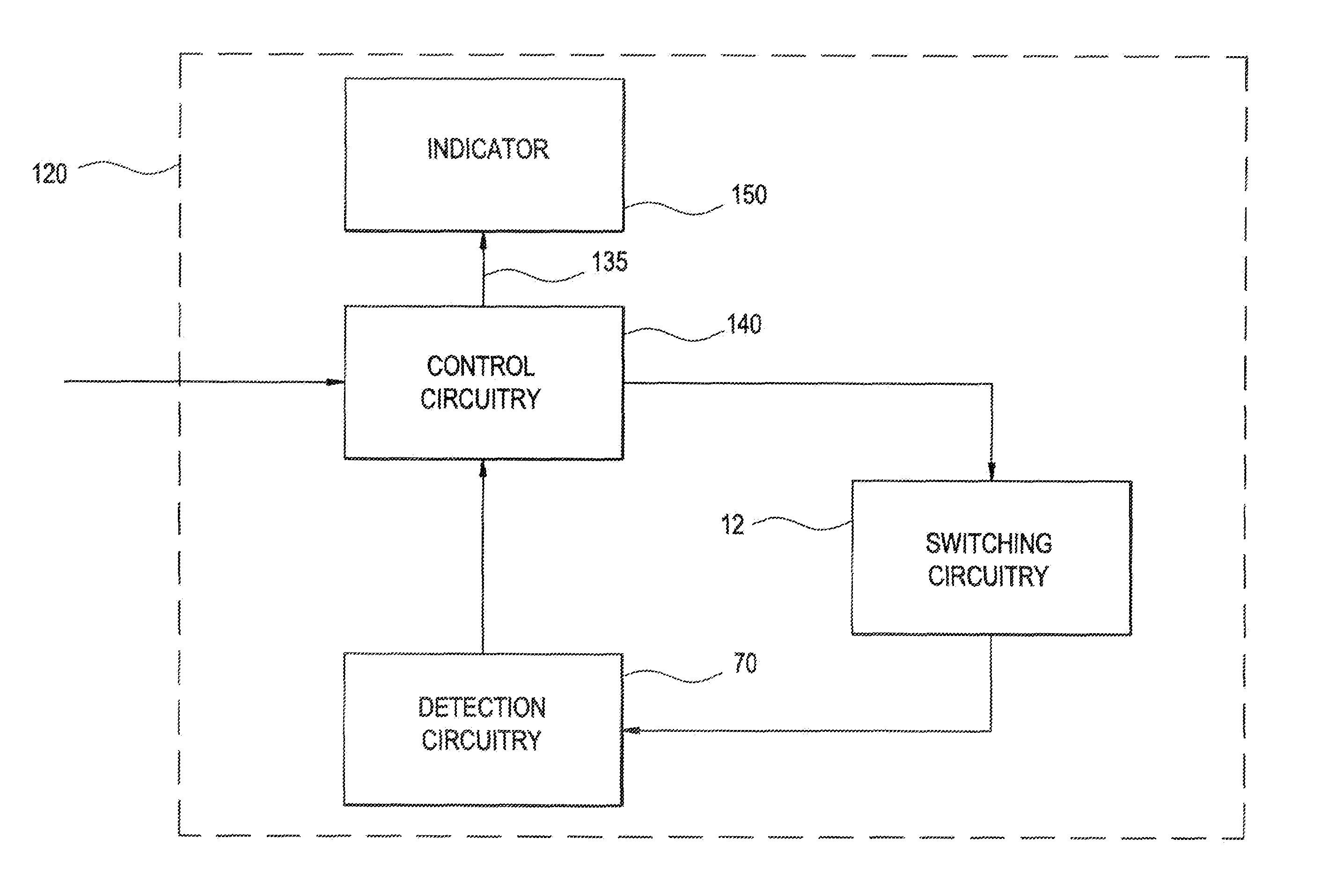
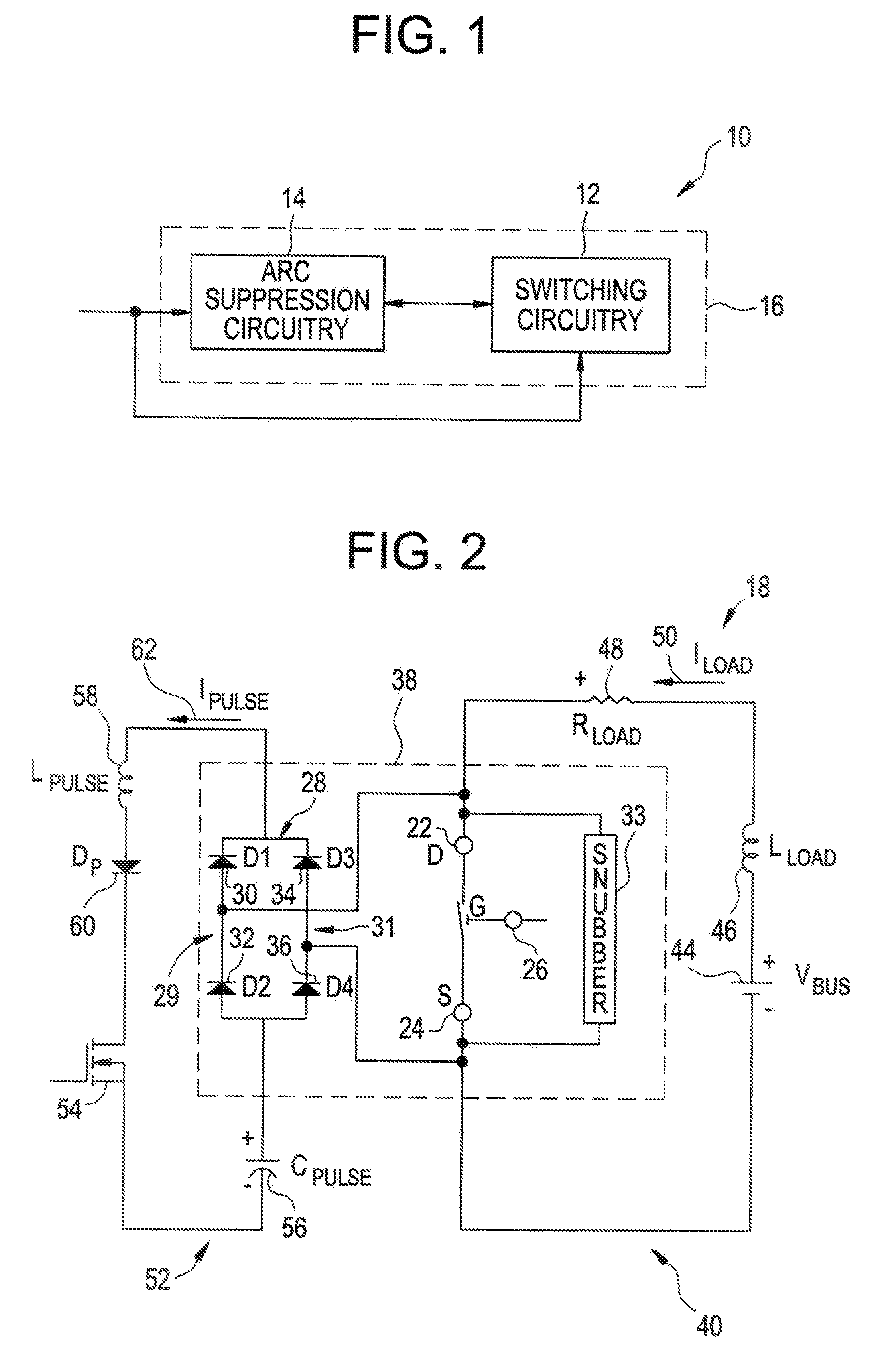
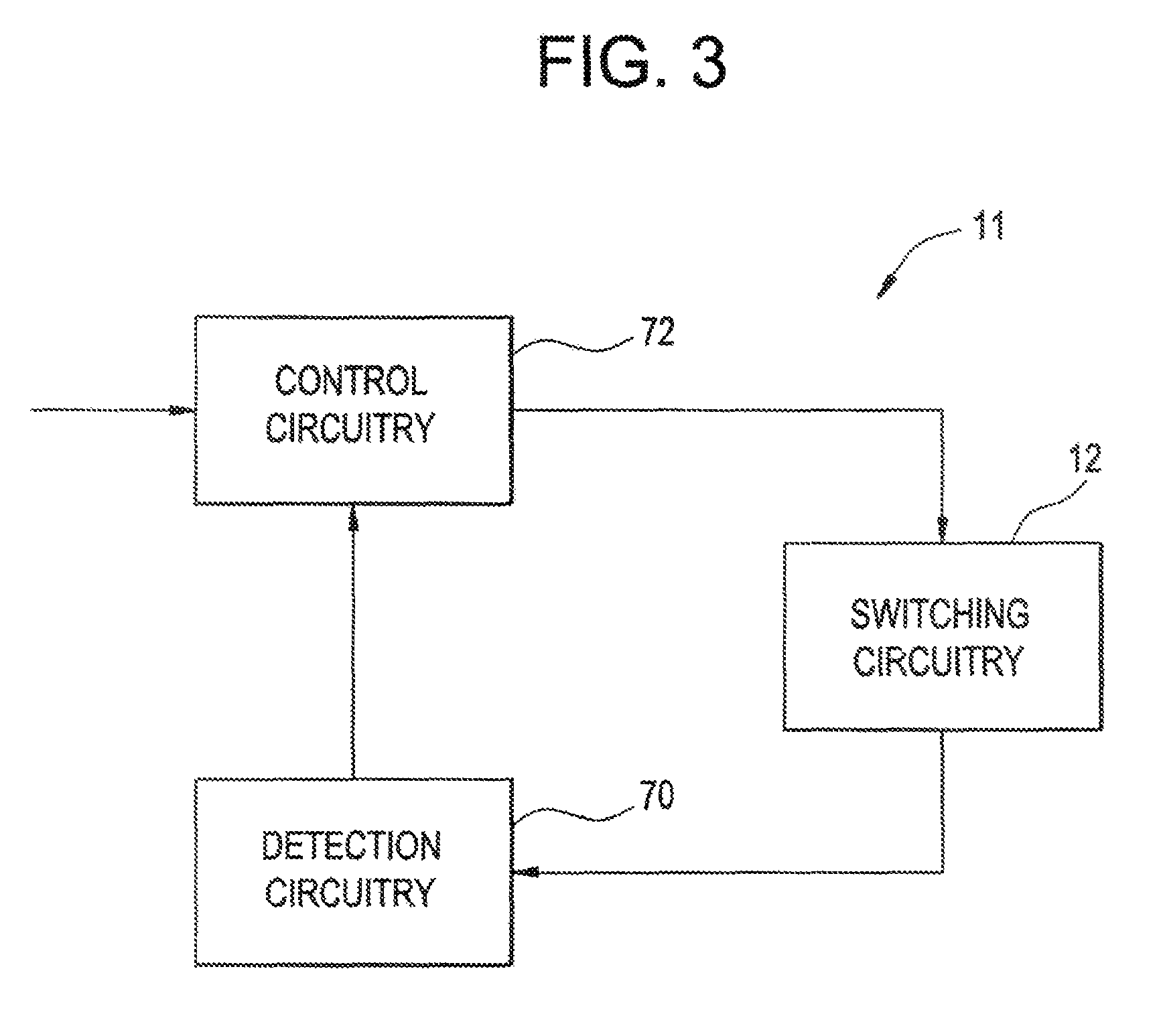
[0020]An embodiment of the invention provides a motor starter with early warning motor protection. The proposed motor starter includes a processor within control circuitry with processor algorithms to determine the possibility of a problem with a motor. Use of micro electromechanical system (MEMS) switches in the motor starter provide fast response time, thereby facilitating diminishing the let-through energy of an interrupted fault. A Hybrid Arcless Limiting Technology (BALI) circuit connected in parallel with the MEMS switches provides capability for the MEMS switches to be opened or closed without arcing at any given time regardless of current or voltage. Therefore, embodiments of the invention provide a motor starter with advantages over conventional systems.

[0021]FIG. 1 illustrates a block diagram of an exemplary arc-less micro-electromechanical system switch (MEMS) based switching system 10, in accordance with aspects of the present invention. Presently. MEMS generally refer t...


PUM


Abstract

A motor starter is disclosed. The motor starter includes control circuitry integrally arranged with at least one current path and a processor included in the control circuitry. The motor starter further includes at least one processor algorithm residing on the processor, the at least one processor algorithm containing instructions to monitor characteristics of current on the at least one current path and to provide data pertaining to a condition of the at least one current path. The motor starter further includes a micro electromechanical system (MEMS) switch disposed on the at least one current path, the MEMS switch responsive to the control circuitry to facilitate the control of an electrical current, passing through the at least one current path.

Description

BACKGROUND OF THE INVENTION[0001]Embodiments of the invention relate generally to a switching device for switching on / off a current in a current path, and more particularly to micro-electromechanical system based switching devices.[0002]A contactor is an electrical device designed to switch an electrical load ON and OFF on command. Traditionally, electromechanical contactors are employed in control gear, where the electromechanical contactors are capable of handling switching currents up to their interrupting capacity. Electromechanical contactors may also find application in power systems for switching currents and in industrial automation systems as motor starters. However, motors controlled by the contactors may fall under a variety of circumstances and fault currents in power systems are typically greater than the interrupting capacity of the electromechanical contactors, Accordingly, to employ electromechanical contactors in power system applications, it may be desirable to pro...

Claims


Application Information

Patent Timeline
Patent Type & Authority Patents(United States)
IPC IPC(8): F21V7/04H02H5/04H02H7/08
CPCH01H59/0009H02P29/02H02H7/0855H02P1/16H01H9/541H01H2071/008
Inventor KUMFER, BRENT CHARLESPREMERLANI, WILLIAM JAMESCAGGLANO, ROBERT JOSEPHSUBRAMANIAN, KANAKASABAPATHILESSLIE, DAVID JAMES
Owner ABB (SCHWEIZ) AG
Why Eureka
Try Eureka