Means of adjusting ground speed of a vehicle based on load on blade assembly

a technology of blade assembly and ground speed, which is applied in the field of vehicle assembly, can solve the problems of high production cost of mowers, exhaust fumes, and leakage of hydraulic fluids that damage tur

Inactive Publication Date: 2009-09-29
SAUER DANFOSS NORDBERG
View PDF15 Cites 62 Cited by
  • Summary
  • Abstract
  • Description
  • Claims
  • Application Information

AI Technical Summary

Problems solved by technology

Not only are these mowers expensive to manufacture, but they produce exhaust fumes and may leak hydraulic fluids that damage the turf.
Still, due to power limitations, operators must exercise caution by reducing ground speed so as not to overload the cutting blade motor when heavy or tall grass is encountered that could stall the motor.

Method used


Image

  • Means of adjusting ground speed of a vehicle based on load on blade assembly
  • Means of adjusting ground speed of a vehicle based on load on blade assembly
  • Means of adjusting ground speed of a vehicle based on load on blade assembly

Examples


Embodiment Construction

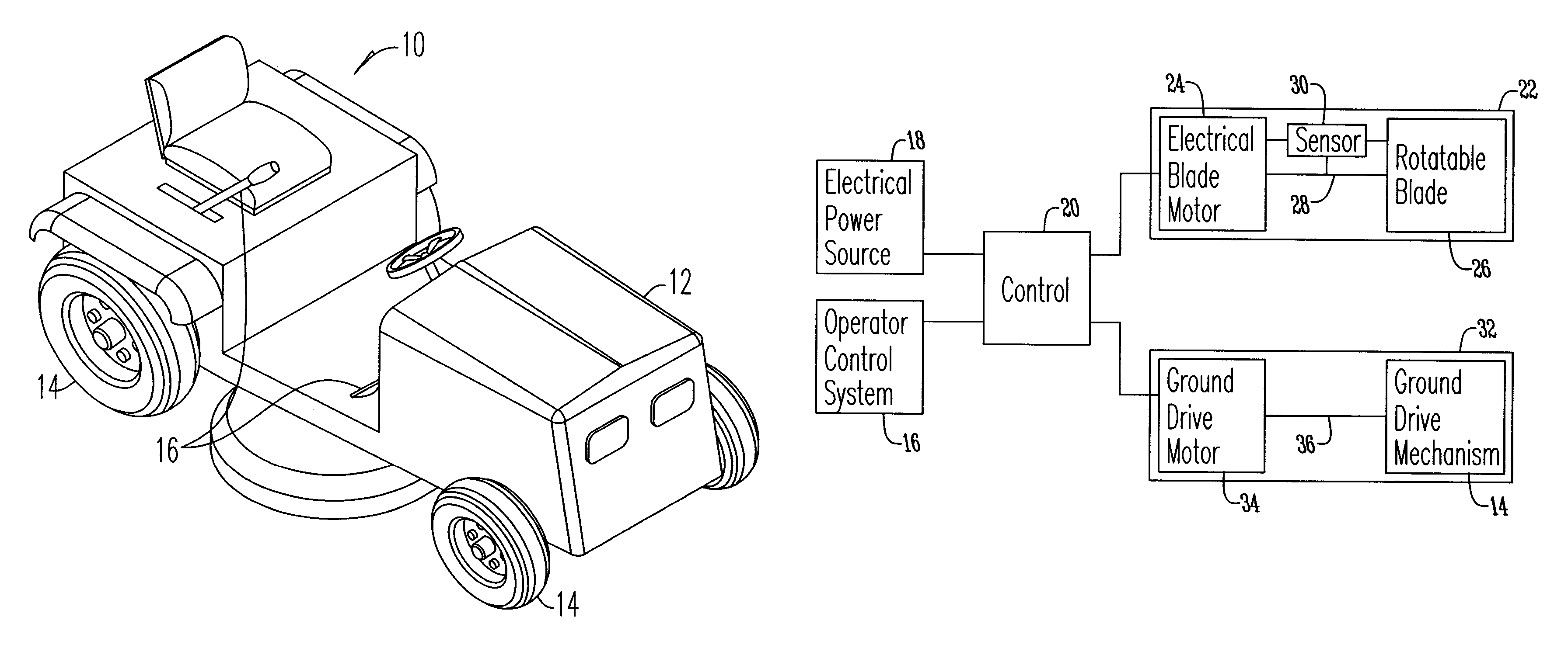
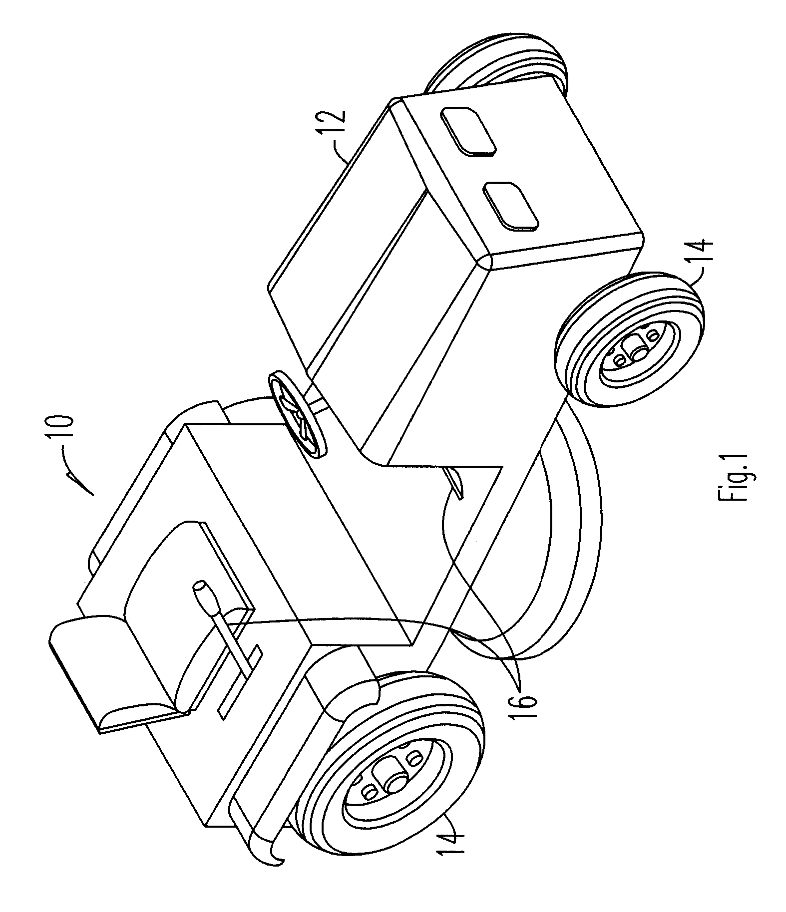
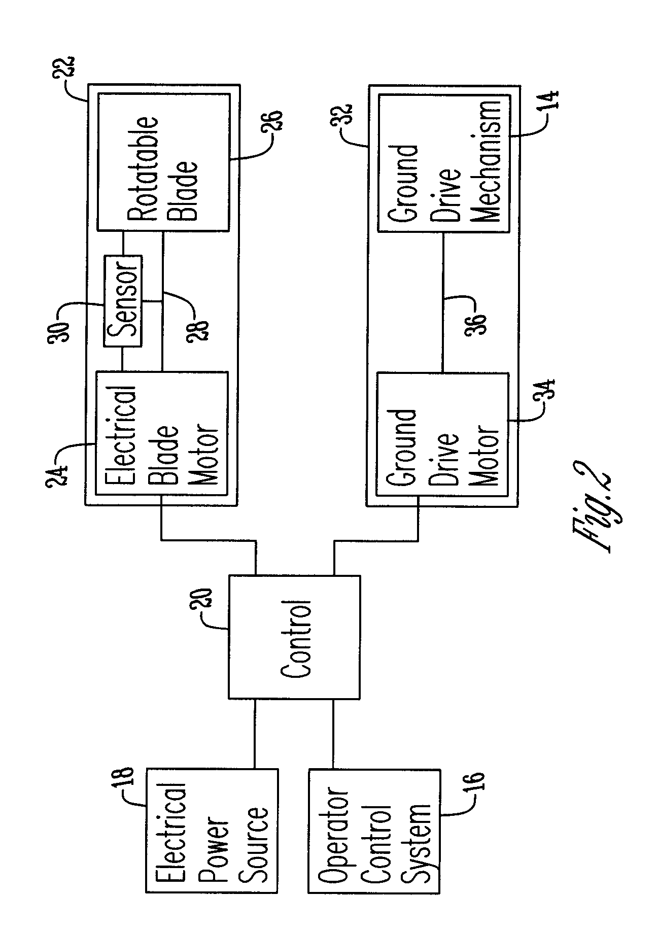
[0012]Referring to the Figures the self-propelled mower assembly 10 has a frame 12 supported by a plurality of ground engaging wheels 14. For purposes of example only, the present invention is shown with regard to a riding mower. The invention may, however, be used for other applications, such as crop harvesting, hedge trimming, other vegetation maintenance, and the like. Mounted on the frame 12 is an operator control system 16 which includes conventional elements for operating a mower 10 such as a steering wheel and mechanism, control module, drive and brake pedals, mower activation and the like. Also mounted to the frame 12 is an electrical power source 18. The electrical power source may be of any type such as a generator, battery, power cord or the like. Both the operator system 16 and the electrical power source 18 are connected to a controller 20 mounted on the frame. The controller 20 is powered by the electrical power source 18 and receives input signals from the operator co...


PUM


Abstract

An assembly having a frame supported by a plurality of ground engaging wheels. Mounted to the frame is an operator control system that is connected to a controller that is powered by an electrical source. The controller is operatively connected to a blade assembly and a ground drive assembly and adjusts the ground speed of the assembly based upon the cutting load of the blade.

Description

BACKGROUND OF THE INVENTION[0001]This invention is directed to a vehicle assembly and more specifically to an assembly that adjusts ground speed based upon the load on a blade assembly.[0002]Riding mowers are known in the art. Most riding mowers are driven mechanically by an internal combustion engine. These engines provide power to both a cutting blade assembly and a drive wheel assembly through adjustable ratio mechanical gearing systems such as variable ratio V-belts and the like. These mowers present certain drawbacks. Not only are these mowers expensive to manufacture, but they produce exhaust fumes and may leak hydraulic fluids that damage the turf.[0003]Electrically powered mowers have addressed some of the these drawbacks. Still, due to power limitations, operators must exercise caution by reducing ground speed so as not to overload the cutting blade motor when heavy or tall grass is encountered that could stall the motor. Accordingly there exists a need in the art for an as...

Claims


Application Information

Patent Timeline
Patent Type & Authority Patents(United States)
IPC IPC(8): A01D34/47
CPCA01D69/02A01D34/006
Inventor JANSEN, LYNN T.GANDRUD, MICHAEL D.
Owner SAUER DANFOSS NORDBERG
Why Eureka
Try Eureka