DC-DC converter control circuit and DC-DC converter control method

a converter control circuit and converter technology, applied in the direction of dc-dc conversion, power conversion systems, instruments, etc., can solve the problems of unstable switching control, inability to make fast response, and risk of abnormal switching action, so as to achieve rapid response

Active Publication Date: 2009-09-29
CYPRESS SEMICON CORP
View PDF9 Cites 6 Cited by
  • Summary
  • Abstract
  • Description
  • Claims
  • Application Information

AI Technical Summary

Benefits of technology

[0014]However, with the DC-to-DC converter control circuit 200, a switching action is executed by detecting a ripple voltage present in the output voltage VOUT, so that in the case of using a capacitor low in the equivalent series-connected resistance ESR as the smoothing capacitor C1 owing to requirements for reduction of an output ripple voltage, there is the likelihood that it becomes difficult to detect variation in the output voltage VOUT, due to a low ripple voltage, thereby raising the risk of rendering switching control unstable, thus posing a problem.
[0021]Accordingly, even if an equivalent series-connected resistance ESR of a smoothing capacitor, connected to an output terminal of the DC-to-DC converter, is reduced, and a voltage ripple superimposed on the output voltage becomes very small in value, it is possible to detect variation in the coil current of the DC-to-DC converter, thereby obtaining an add-up signal obtained by adding a variation component of the coil current to the output voltage. By comparing the add-up signal with a reference signal, variation in the coil current, due to a change in load, can be captured with reliability.
[0022]Because the add-up signal is outputted according to the variation component of the coil current IL, there is an increase in difference between the add-up signal and the reference signal in the initial stage of a sudden change in load, so that switching control rapidly responding to the sudden change in load is executed. It is possible to rapidly cope with a change in the coil current, and deviation of the output voltage from a target voltage, accompanying a change in load, in rapid response to a steep change in load.
[0023]As switching control rapidly responding to the sudden change in load is executed, and the coil current, and the output voltage approach respective target values, so decreased is a difference between the add-up signal and the reference signal, and transient switching control undergoes gradual convergence by degrees. In coincidence with reaching a steady state, the transient switching control comes to an end, thereby enabling a phenomenon of the output voltage overshooting in a reverse direction, accompanied by a ringing phenomenon of the output voltage to be prevented.

Problems solved by technology

That is, unless a feedback response frequency band according to the output voltage VOUT is sufficiently lowered in comparison with the switching frequency, there is the risk of an abnormal switching action taking place.
Accordingly, there is the likelihood that it is not possible to make fast response to a sudden change in load, thus posing a problem.
However, with the DC-to-DC converter control circuit 200, a switching action is executed by detecting a ripple voltage present in the output voltage VOUT, so that in the case of using a capacitor low in the equivalent series-connected resistance ESR as the smoothing capacitor C1 owing to requirements for reduction of an output ripple voltage, there is the likelihood that it becomes difficult to detect variation in the output voltage VOUT, due to a low ripple voltage, thereby raising the risk of rendering switching control unstable, thus posing a problem.
Furthermore, with the DC-to-DC converter control circuit 200, although fast response against the sudden change in load is enabled, a condition of fast response continues even in a stage where a transient response accompanying the sudden change in load comes to an end, so that there is the likelihood that the output voltage of the DC-to-DC converter overshoots a target voltage, subsequently causing a ringing phenomenon, which is a problem.
In addition, since the comparator control method is in principle the fixed pulse width method, there is another problem that it becomes difficult to implement the frequency fixing method easy in establishing countermeasures against noise.

Method used


Image

  • DC-DC converter control circuit and DC-DC converter control method
  • DC-DC converter control circuit and DC-DC converter control method
  • DC-DC converter control circuit and DC-DC converter control method

Examples


first embodiment

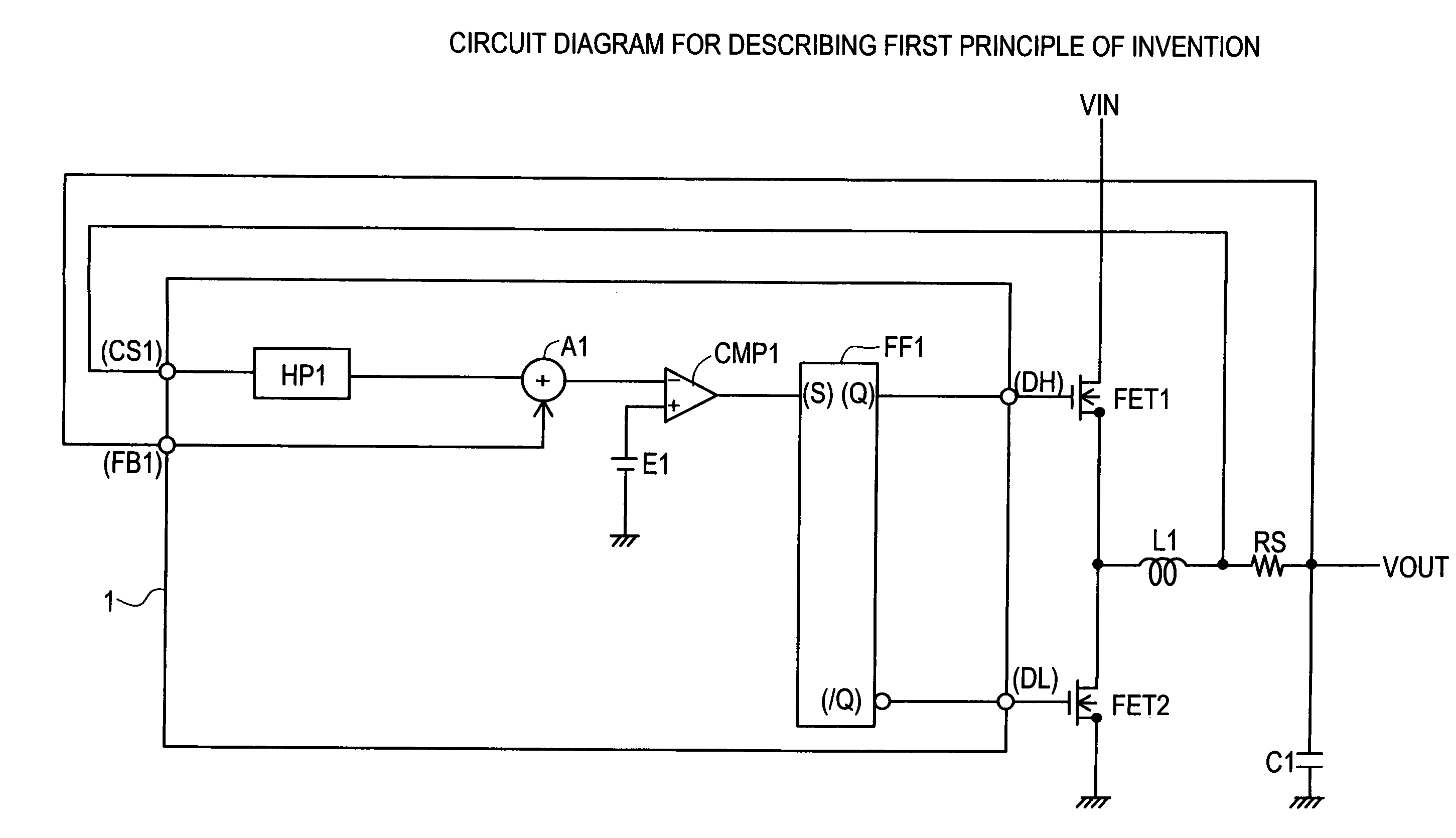
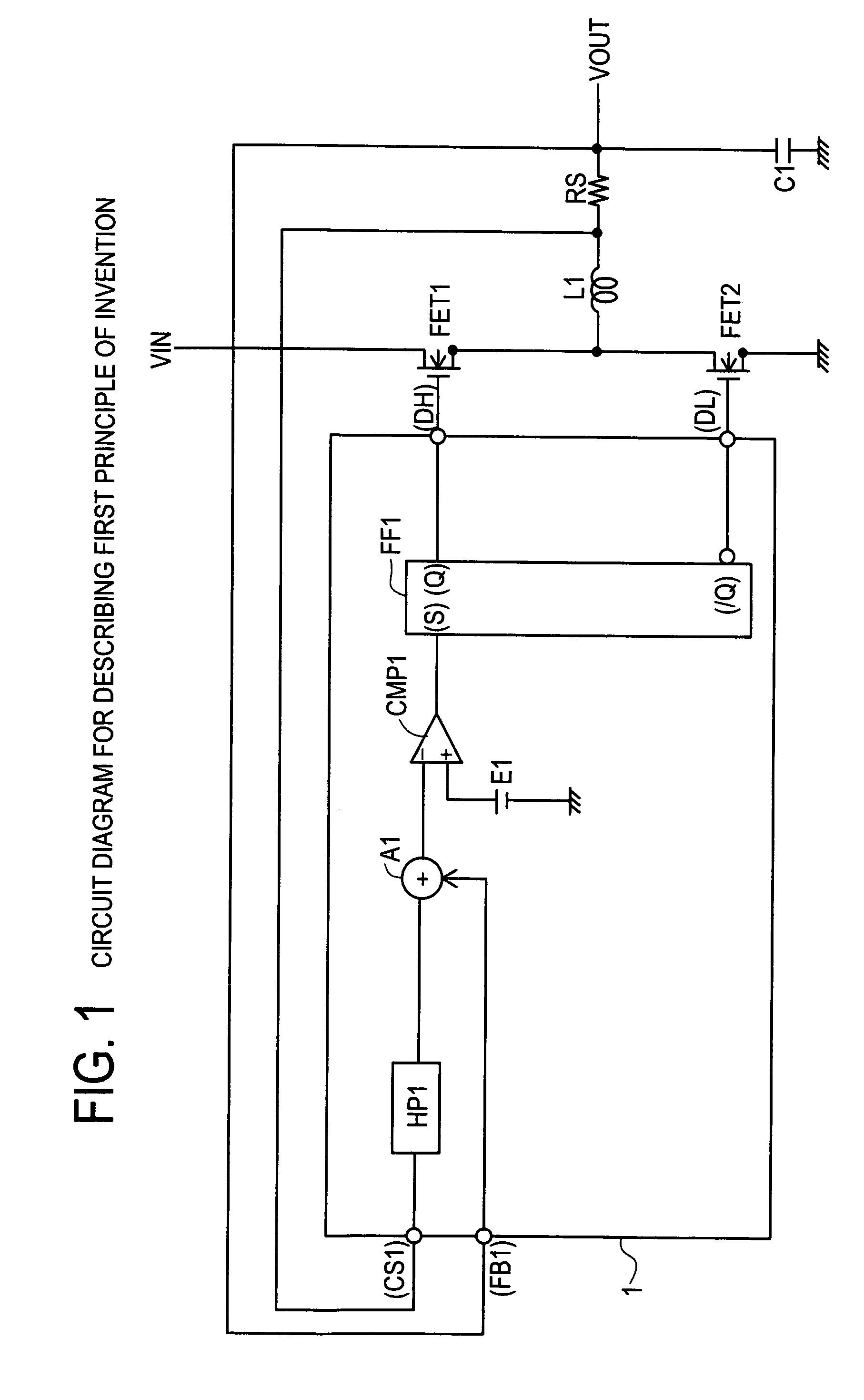
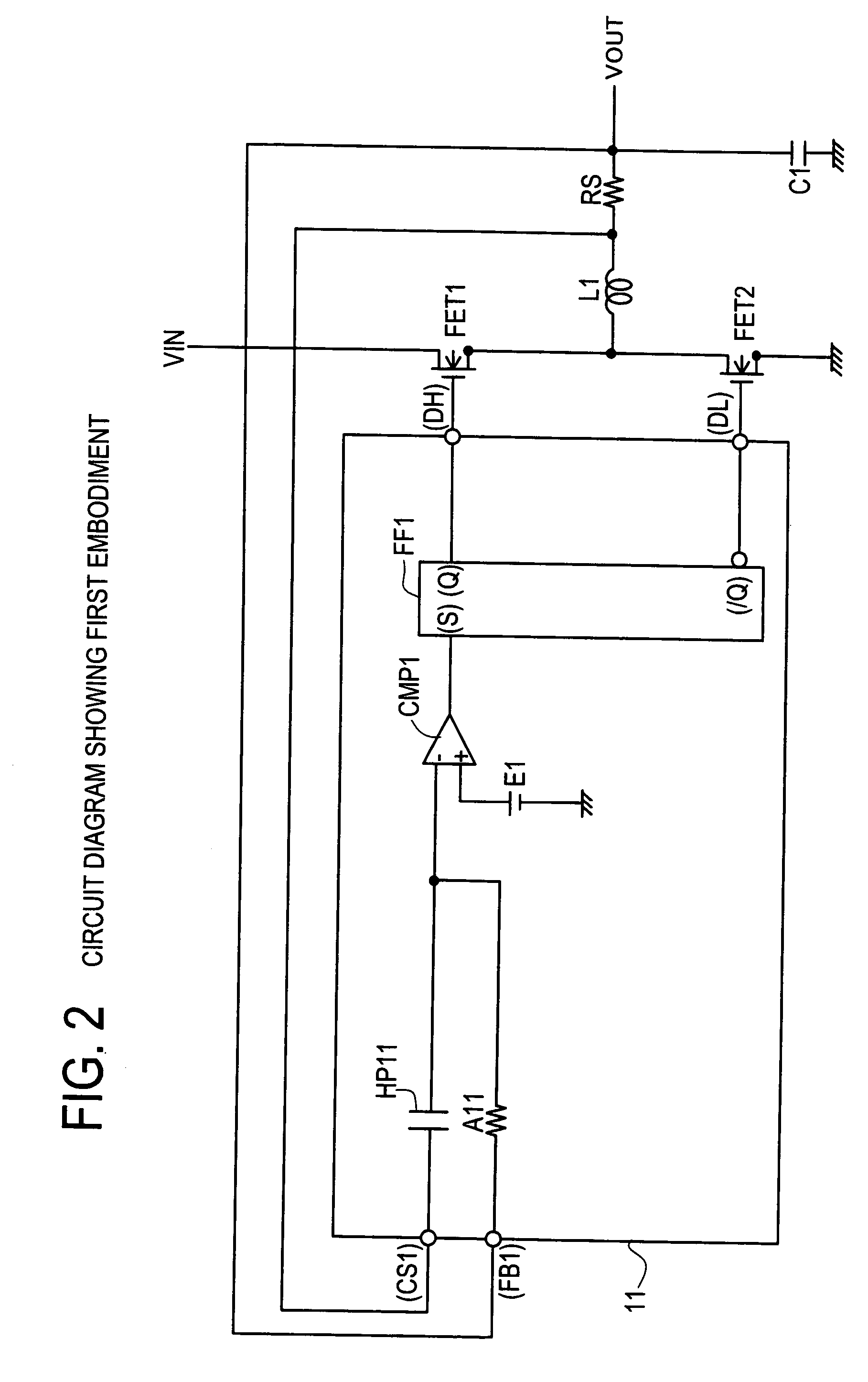
[0041]FIG. 2 shows a circuit diagram of the invention, embodying the first principle shown in FIG. 1. With a DC-to-DC converter control circuit 11, a high-pass filter capacitor HP11 as a specific example of the high-pass filter HP1 is provided between an input terminal (CS1), and an inverting input terminal of a comparator CMP1. Further, an add-up resistor A11 doubling as a constituent element of a high-pass filter is provided between an input terminal FB1, and the inverting input terminal of the comparator CMP1.

[0042]The add-up resistor A11 represents a specific example of the adder A1. A variation component of a coil current, that is, an AC signal component of a signal inputted from the input terminal CS1, passing through the high-pass filter capacitor HP11, is inputted from the input terminal FB1 to be added to an output voltage VOUT, that is, a DC signal component, passing through the add-up resistor A11. A high-pass filter bandwidth is dependent on HP11, and A11.

[0043]An add-up...

second embodiment

[0052]FIG. 4 shows a circuit diagram of the invention, embodying the second principle (FIG. 3). With a DC-to-DC converter control circuit 21, there are provided a sampling circuit LP21 as an example of the low-pass filter LP2 in the case of the second principle, an inverting amplifier IA21 as an example of the inverting amplifier IA2, and an adder A21 as an example of the adder A2. In addition, there is provided a noninverting amplifier 31 for amplifying a voltage signal VP against a signal inputted to an input terminal (CS1) before outputting the same.

[0053]The noninverting amplifier 31 is a common noninverting amplifier made up of an amplifier AMP1, and resistors R1, R2. Assuming that respective resistance values of the resistors R1, R2 are R1, R2, the noninverting amplifier 31 has a gain G=1+R2 / R1. An output voltage VOUT is inputted to the resistor R1 via an input terminal (FB1). The output voltage VOUT can be deemed as a DC signal component of variation in a coil current, due to...


PUM


Abstract

In a DC-to-DC converter control circuit and control method thereof, an arithmetic circuit for outputs an add-up signal generated by adding an output voltage signal obtained by adding an output voltage of a DC-to-DC converter and an AC current signal obtained according to an AC current component of a coil current, and a comparator compares the add-up signal with a reference signal. Switching control is executed according to a result of the comparison by the comparator. By the control circuit and method, variations in the coil current due to a change in load may be reliably captured by comparing the add-up signal with the reference signal, and compatibility between low ripple voltage characteristics and stable and fast response to sudden changes in load may be achieved.

Description

CROSS-REFERENCE TO RELATED APPLICATIONS[0001]This application is based upon and claims the benefit of priority from each of the prior Japanese Patent Application No. 2005-367136 filed on Dec. 20, 2005, the entire contents of which are incorporated herein by reference.BACKGROUND OF THE INVENTION[0002]1. Field of the Invention[0003]The invention relates to a DC-to-DC converter control circuit having fast response characteristics against a sudden change in load, and a DC-to-DC converter control method using the same, and in particular, to a DC-to-DC converter control circuit aiming at compatibility with low ripple voltage characteristics, and a DC-to-DC converter control method using the same.[0004]2. Description of the Related Art[0005]FIG. 7 shows a current control type DC-to-DC converter circuit. It has a configuration wherein switching control by a synchronous rectification method is executed by a main transistor FET1 and a synchronous transistor FET2, interconnecting an input volt...

Claims


Application Information

Patent Timeline
Patent Type & Authority Patents(United States)
IPC IPC(8): G05F1/575
CPCH02M3/158H02M2001/0019H02M2001/0009H02M1/0009H02M1/0019
Inventor NISHIMORI, EIJI
Owner CYPRESS SEMICON CORP
Why Eureka
Try Eureka