Dust collection apparatus for vacuum cleaner

a technology for vacuum cleaners and dust collection equipment, which is applied in the field of vacuum cleaners, can solve the problems of deteriorating dust collection efficiency and contaminant collection in the dust collection chamber

Inactive Publication Date: 2009-10-06
SAMSUNG GWANGJU ELECTRONICS CO LTD
View PDF7 Cites 96 Cited by
  • Summary
  • Abstract
  • Description
  • Claims
  • Application Information

AI Technical Summary

Benefits of technology

[0007]An object of the present invention is to solve at least the above problems and / or disadvantages and to provide at least the advantages described below. Accordingly, an object of the present invention is to provide a dust collecting apparatus of a vacuum cleaner, which can prevent contaminants separated in a cyclone chamber from being discharged to the outside of the dust collecting apparatus.
[0009]Accordingly, since the cyclone chamber and the contaminant collecting chamber are formed independently, it is possible to prevent contaminants collected in the contaminant collecting chamber from being re-scattered by an air flow and from entering the cyclone chamber.
[0014]The support body is formed into a ring shape and is disposed between the upper case and the contaminant collecting receptacle, the supporting ribs are provided radially about the cyclone case. Also, a portion of the support body is protruded to an inside of the cyclone body, at least one of the support body and the supporting ribs prevent the contaminant in the contaminant collecting chamber from flowing to the upper case when the cyclone body is inclined.

Problems solved by technology

In addition, when the position of the vacuum is changed, contaminants collected in the contaminant collecting chamber may flow out from the dust collecting apparatus.
Thus, the conventional dust collecting apparatus has a problem: deteriorating dust collection efficiency due to this outflow of contaminants.

Method used


Image

  • Dust collection apparatus for vacuum cleaner
  • Dust collection apparatus for vacuum cleaner
  • Dust collection apparatus for vacuum cleaner

Examples


Embodiment Construction

[0024]Hereinafter, an embodiment of the present invention will be described in detail with reference to the accompanying drawing figures.

[0025]In the following description, same drawing reference numerals are used for the same elements even in different drawings. The matters defined in the description such as a detailed construction and elements are nothing but the ones provided to assist in a comprehensive understanding of the invention. Thus, it is apparent that the present invention can be carried out without those defined matters. Also, well-known functions or constructions are not described in detail since they would obscure the invention in unnecessary detail.

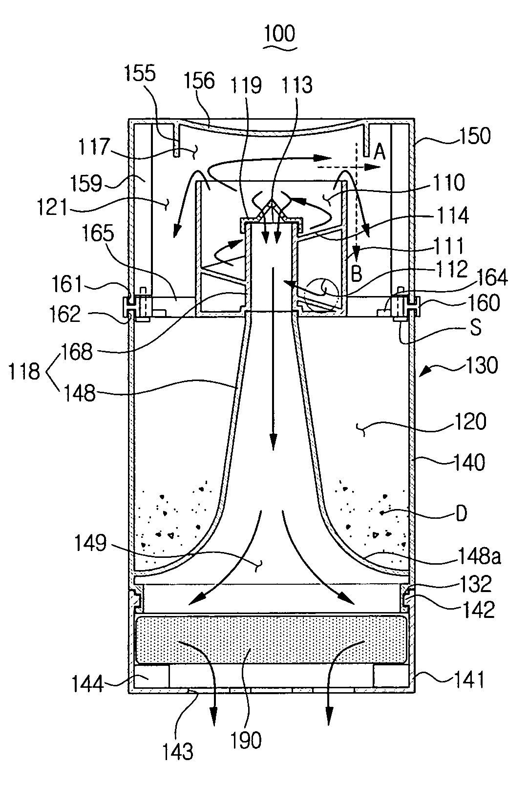
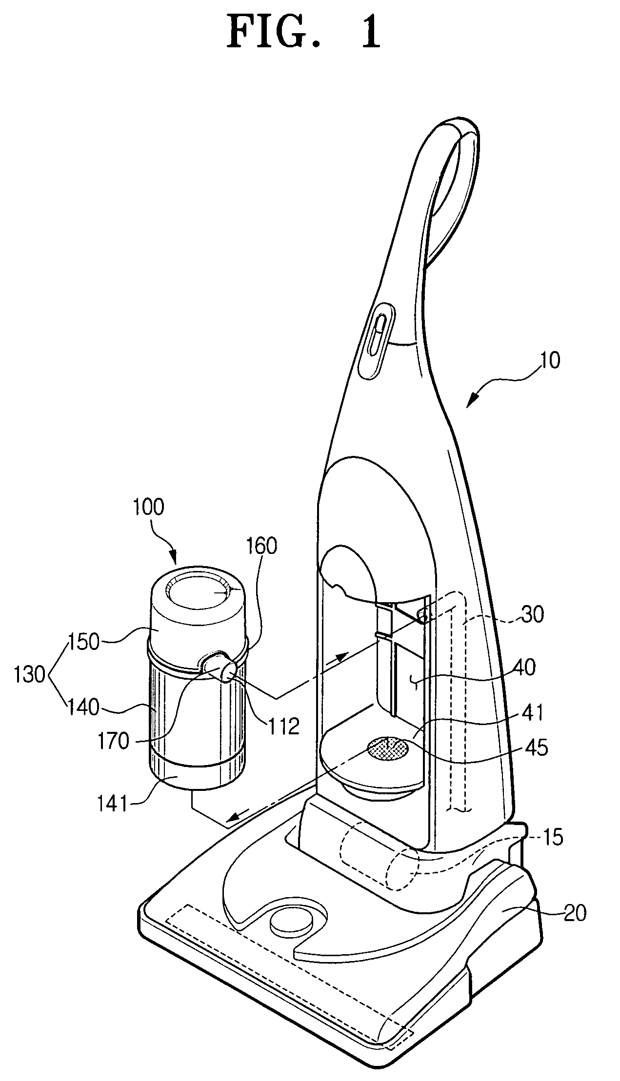
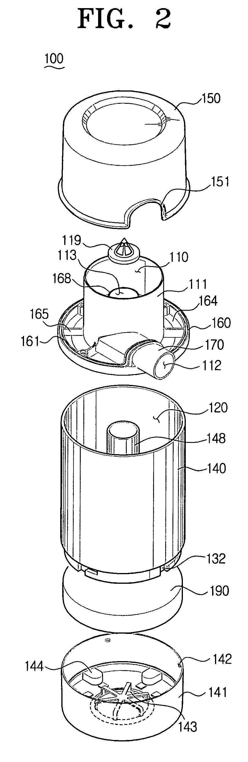
[0026]Referring to FIG. 1 through FIG. 4, a dust collecting apparatus 100, adapted for use in a vacuum cleaner 10, comprises a cyclone body 130, an air inflow tube 170, and an air outlet tube 118.

[0027]The cyclone body 130 is provided with an upper case 150, a contaminant collecting receptacle 140 and a cyclone case 111.

[...


PUM

PropertyMeasurementUnit
centrifugal forceaaaaaaaaaa
weightaaaaaaaaaa
inner diameteraaaaaaaaaa

Abstract

A dust collecting apparatus for a vacuum cleaner including a cyclone body provided with a cyclone chamber and a contaminant collecting chamber formed therein, a cyclone case provided in the cyclone body having the cyclone chamber and the contaminant collecting chamber separated from each other; an air inflow tube penetrating an outer wall of the cyclone body such that a suction passage at an outside of the cyclone body is fluidly communicated with a lower end of the cyclone chamber; and an air outlet tube penetrating sequentially a bottom of the cyclone case and a bottom the cyclone body to guide the air discharged from the cyclone chamber to a discharge passage placed at an outside of the cyclone body, wherein the contaminant collecting chamber is connected to the cyclone chamber through a contaminant discharge port formed at a side surface of upper end of the cyclone chamber.

Description

CROSS-REFERENCE TO RELATED APPLICATIONS[0001]This application claims the benefit of U.S. Provisional Application No. 60 / 698,449 filed on Jul. 12, 2005 in the United States Patent and Trademark Office, and claims the benefit of Korean Patent Application No. 2005-74952 filed on Aug. 16, 2005 in the Korean Intellectual Property Office, the entire contents of each of these applications is incorporated herein by reference.BACKGROUND OF THE INVENTION[0002]1. Field of the Invention[0003]The present invention relates to a vacuum cleaner. More particularly, the present invention relates to a dust collecting apparatus for a vacuum cleaner for separating contaminants from drawn-in air.[0004]2. Description of the Related Art[0005]In general, a vacuum cleaner is an apparatus for cleaning a surface by drawing in contaminants on the surface being cleaned along with ambient air and separating the contaminants from the drawn-in air. Such a vacuum cleaner comprises a dust collecting apparatus for col...

Claims


Application Information

Patent Timeline
Patent Type & Authority Patents(United States)
IPC IPC(8): B01D45/12
CPCA47L9/1683A47L9/1666Y10S55/03A47L9/16A47L9/10
Inventor YOO, DONG-HUNCHOUNG, MYOUNG-SUNYOU, JAE-SUN
Owner SAMSUNG GWANGJU ELECTRONICS CO LTD
Why Eureka
Try Eureka