Methods for imaging regular patterns

a pattern and pattern technology, applied in the field of imaging systems, can solve the problems of reducing the overall process yield, increasing the cost of finished products, and color filter fabrication can be a very expensive process, and achieve the effect of reducing the visual banding occurring

Active Publication Date: 2009-10-06
KODAK CANADA ULC
View PDF9 Cites 9 Cited by
  • Summary
  • Abstract
  • Description
  • Claims
  • Application Information

AI Technical Summary

Benefits of technology

[0008]In accordance with the present invention, methods for imaging a regular pattern of features are provided that reduce the visual banding occurring at swath boundaries by configuring the number of channels in the imaging swath to ensure that the boundary does not occur within a visible portion of an imaged feature.

Problems solved by technology

By nature these fabrication processes involve a large number of separate steps, each step commonly having a finite risk of failure, thus reducing the overall process yield and increasing the cost of the finished article.
Color filter fabrication can be a very expensive process because of the high cost of materials and low process yield.
One problem with multi-channel imaging systems is that it is extremely difficult to ensure that all channels have identical imaging characteristics.
These pronounced swath boundary discontinuities may lead to objectionable visual artifacts when viewing a color filter that has been produced by a dye transfer method.
However, thermal and mechanical drifts may result in banding re-appearing after some time.

Method used


Image

  • Methods for imaging regular patterns
  • Methods for imaging regular patterns
  • Methods for imaging regular patterns

Examples


example

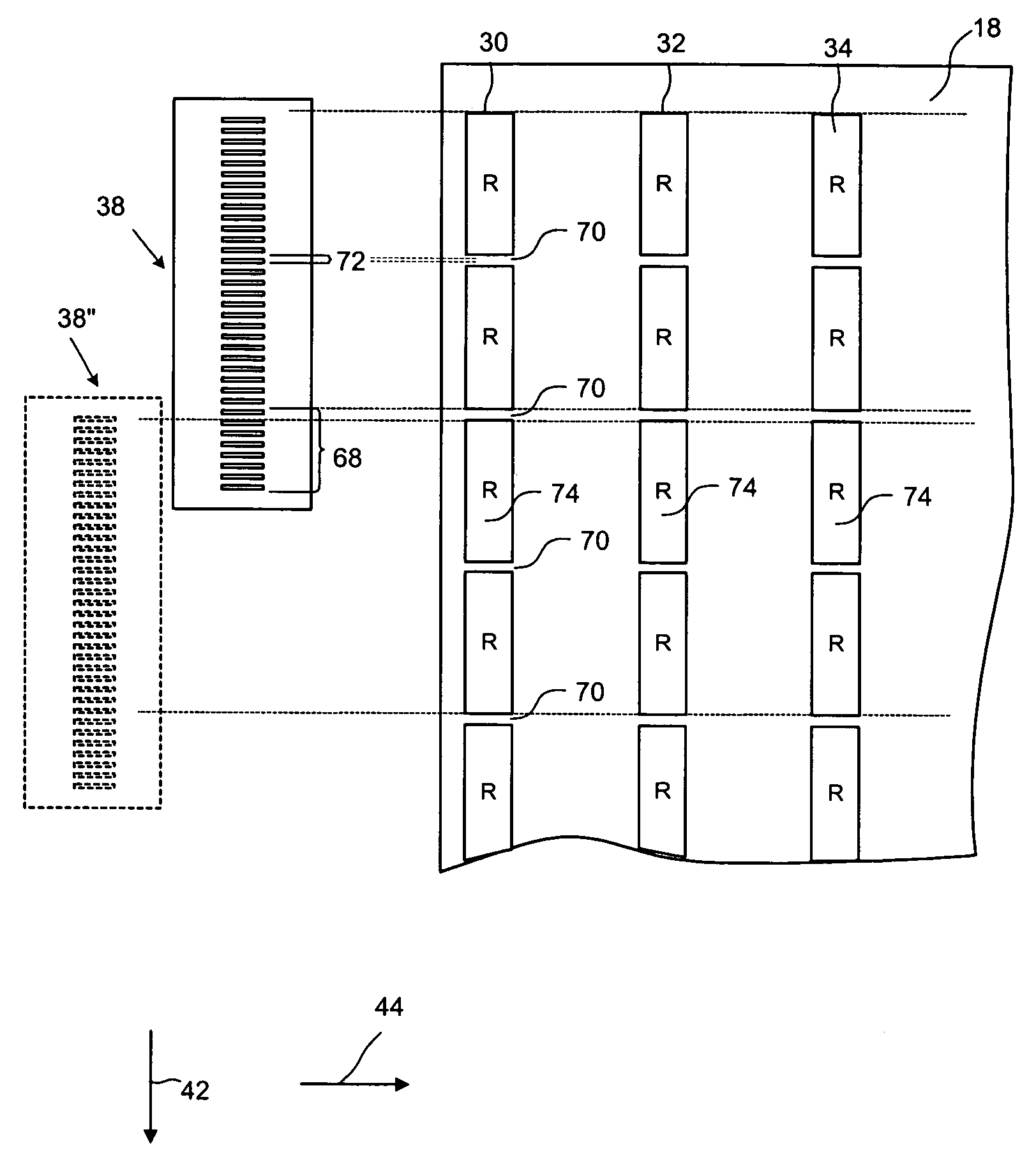
[0050]An 11×13 inch three color image was prepared for a 1200 dpi imaging head with 224 available channels. The target width of each imaged color element stripe was 84.6 μm corresponding to 4 channels on the imaging head. The spacing between adjacent stripes of different color was one channel, or 21.167 μm. The imaging head used was a SQUAREspot® thermal imaging head manufactured by Creo Inc. of Burnaby, British Columbia, Canada. The head was mounted on the flatbed scanner as described in the paper “Thermal Transfer for Flat Panel Display Manufacturing”, Eran Elizur and Dan Gelbart, Journal of the Society for Information Display, Vol. 11 Number 1, pp. 199-202.

[0051]The imaging head interface allows configuration of the number of imaging channels, but only in groups of 8. The chosen pattern repeat of 4 channels on and 1 channel off further constrains the number of channels to being a multiple of 40 (5×8=40 channels). The largest number of channels that may be used on this particular ...


PUM

PropertyMeasurementUnit
poweraaaaaaaaaa
temperaturesaaaaaaaaaa
lengthaaaaaaaaaa

Abstract

Methods for imaging regular patterns are provided. A multi-channel imaging head is configured in accordance with the repeat of a pre-determined regular pattern such that no swath boundaries appear within the visibly imaged features of the pattern. The imaged articles have reduced visible banding due to the elimination of swath boundaries in the imaged features.

Description

CROSS REFERENCE TO RELATED APPLICATION[0001]This Application claims the benefit under 35 USC 119(e) of U.S. Provisional Patent Application No. 60 / 539,338, filed Jan. 28, 2004, which is hereby incorporated by reference herein in its entirety. The subject matter of this invention was made under a Cooperative Development Agreement between Creo Products Inc. (now known as Kodak Graphic Communications Canada Company) and E. I. du Pont de Nemours and Company dated Oct. 1, 2001.FIELD OF THE INVENTION[0002]The present invention relates to imaging systems and more particularly to methods of imaging regular patterns in an imaging system.BACKGROUND OF THE INVENTION[0003]Commonly employed fabrication techniques for displays and semiconductor electronic devices involve several imaging steps. A color filter substrate coated with a resist or other sensitive material is exposed to radiation through a photo-tool mask to effect some change. By nature these fabrication processes involve a large number...

Claims


Application Information

Patent Timeline
Patent Type & Authority Patents(United States)
IPC IPC(8): G02B5/20G02F1/13B41J2/21G02F1/1335G03F9/00G06K15/02G06K15/10G06K15/12H05K3/10
CPCG02B5/201G06K15/107G06K15/1261G06K15/029G02F1/133516G06K2215/111G02B5/20G02F1/1335G06K15/02
Inventor CASPAR, JONATHAN V.ZWICKER, HARRY RICHARD
Owner KODAK CANADA ULC
Why Eureka
Try Eureka