
Method and system for automatic intra-oral sensor locating for image acquisition

a sensor and image acquisition technology, applied in the field of digital imaging, can solve the problems of io sensor not being properly positioned to acquire the desired tooth image, waste of time,

Inactive Publication Date: 2009-10-06
APTERYX LLC
View PDF15 Cites 9 Cited by
  • Summary
  • Abstract
  • Description
  • Claims
  • Application Information

AI Technical Summary

Benefits of technology

"The present invention provides a method and system for capturing intra-oral digital images. The method involves establishing a spatial frame-of-reference with respect to teeth within a mouth of a patient and placing an intra-oral digital imaging sensor within the mouth of the patient adjacent to at least one tooth within the mouth that is to be imaged by the intra-oral sensor. The method also includes automatically generating first spatial location information defining how the intra-oral sensor is placed with respect to the spatial frame-of-reference. The system includes a means for acquiring a first digital image of the at least one tooth with the intra-oral sensor and automatically associating the first spatial location information with the first digital image. The technical effects of this invention include improved accuracy and efficiency in capturing intra-oral digital images and reduced discomfort for the patient."

Problems solved by technology

Having to manually interact with a user interface of the system between each image acquisition wastes time and calls into question whether the user is truly remaining sanitary for each acquisition (i.e., each time the user has to re-position the sensor in the patient's mouth).
Also, when the user positions the IO sensor in the mouth of the patient, the IO sensor may or may not be properly positioned to acquire an image of the desired tooth or teeth.

Method used


Image

  • Method and system for automatic intra-oral sensor locating for image acquisition
  • Method and system for automatic intra-oral sensor locating for image acquisition
  • Method and system for automatic intra-oral sensor locating for image acquisition

Examples


Embodiment Construction

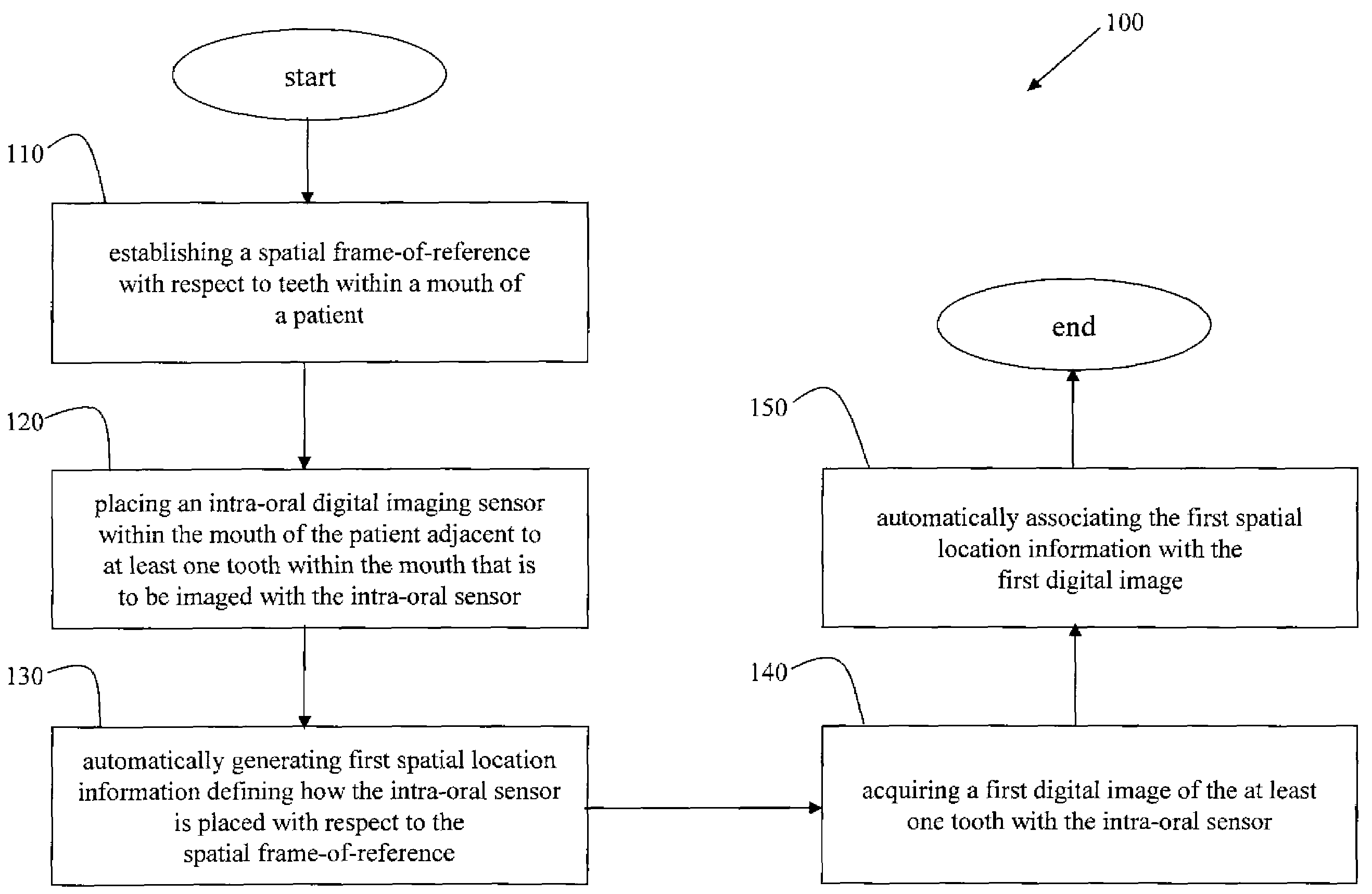
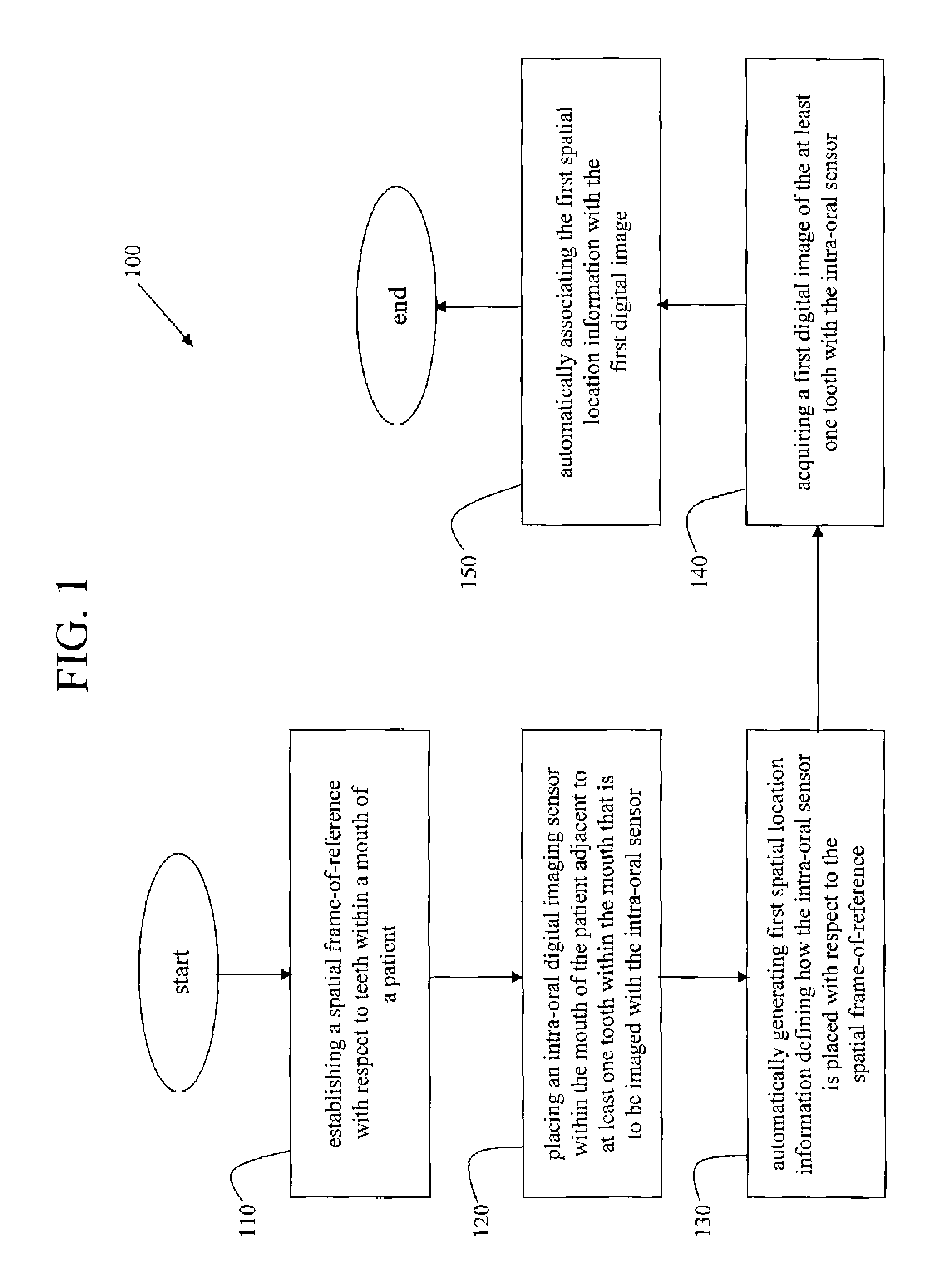
[0018]FIG. 1 is a flowchart of an embodiment of a method 100 of capturing intra-oral digital images, in accordance with various aspects of the present invention. In step 110, a spatial frame-of-reference is established with respect to teeth within a mouth of a patient. In step 120, an intra-oral digital imaging sensor is placed within the mouth of the patient adjacent to at least one tooth within the mouth that is to be imaged using the intra-oral sensor. In step 130, first spatial location information is automatically generated, defining how the intra-oral sensor is placed in the mouth with respect to the spatial frame-of-reference. In step 140, a first digital image of the at least one tooth is acquired using the intra-oral sensor. In step 150, the first spatial location information is automatically associated with the first digital image.

[0019]Using the method 100 of FIG. 1, a dentist or technician does not have to manually interact with the image acquisition system to tell the s...


PUM


Abstract

A method and systems for capturing digital intra-oral images, while automatically determining a location of an intra-oral sensor placed within a mouth of a patient, is disclosed. A spatial frame-of-reference is established with respect to teeth within the mouth of the patient. An intra-oral digital imaging sensor is placed within the mouth of the patient adjacent to at least one tooth within the mouth that is to be imaged using the intra-oral sensor. Spatial location information is automatically generated such that the spatial location information defines how the intra-oral sensor is placed with respect to the spatial frame-of-reference. A digital image of the at least one tooth is acquired using the intra-oral sensor and the spatial location information is automatically associated with the acquired digital image. The associated spatial location information may be used to automatically correlate the acquired image to a tooth or teeth within the mouth and / or to automatically orient the acquired image for display.

Description

CROSS-REFERENCE TO RELATED APPLICATIONS / INCORPORATION BY REFERENCE[0001]U.S. patent application Ser. No. 11 / 078,810 filed on Mar. 11, 2005 is incorporated herein by reference in its entirety.TECHNICAL FIELD[0002]Certain embodiments of the present invention relate to digital imaging. More particularly, certain embodiments of the present invention relate to methods and systems for acquiring intra-oral digital images by automatically determining where in a patient's mouth an intra-oral digital imaging sensor has been placed.BACKGROUND OF THE INVENTION[0003]Today, the process for capturing intra-oral digital images typically involves having to manually tell the system for which tooth or teeth an image is being captured. The system will typically prompt the user (e.g., a dentist or a technician) to tell the system which teeth are about to be imaged, based on where an intra-oral (IO) sensor has been placed in the mouth of a patient.[0004]For example, an x-ray technician may place an intra...

Claims


Application Information

Patent Timeline
Patent Type & Authority Patents(United States)
IPC IPC(8): G06K9/00A61B6/51G06V10/22
CPCA61B6/145G06K9/2054A61B6/547A61B8/12G06V10/22A61B6/512
Inventor CRUCS, KEVIN M.
Owner APTERYX LLC
Learn More