Multi-stage trigger for automatic weapons

a multi-stage, automatic weapon technology, applied in the direction of breech mechanism, small arms, ammunition loading, etc., can solve the problems of loss of life, unsecured threaded screws such as those found in the u.s., 324 (arnold w. jewell) having a tendency to become threadedly unsecured after prolonged use, etc., to facilitate a consistent trigger pull weight, easy and cost-effective manufacturing, simple and robust sheet metal disconnector

Active Publication Date: 2009-10-13
WHG PROPERTIES
View PDF7 Cites 100 Cited by
  • Summary
  • Abstract
  • Description
  • Claims
  • Application Information

AI Technical Summary

Problems solved by technology

Reducing the trigger pull weight also presents the potential for accidental or negligent discharges which can result in the loss of life, which is of particular concern to law enforcement and military end users.
Unfortunately many existing designs require the adjustment of set screws and / or the reduction of spring tension necessary to operate the hammer component of the trigger assembly.
Set screws such as those found in U.S. Pat. No. 6,131,324 (Arnold W. Jewell) have a tendency to become threadedly unsecured after prolonged use.
This often leads to a situation where the trigger either allows the uncontrolled discharge of the host weapon or prohibits the weapons from firing at all, this presents an obvious safety problem and concern for the user of a firearm equipped with such a trigger.
These designs have a flat surface to surface contact which in the case of a pivoting component contacting another stationary component a flat surface to surface contact is extremely difficult to achieve as any deviation from perfect component size will in fact cause the two surfaces to not sit flat to each other thereby negatively affecting the primary sear engagement thus affecting the trigger pull weight.
Any inconsistency between these two flat surfaces will dramatically and negatively affect the trigger mechanism as a whole.
Many available triggers on the market do not have a secondary safety sear which would prevent the firearm from discharging should the primary sear break.

Method used


Image

  • Multi-stage trigger for automatic weapons
  • Multi-stage trigger for automatic weapons
  • Multi-stage trigger for automatic weapons

Examples


Embodiment Construction

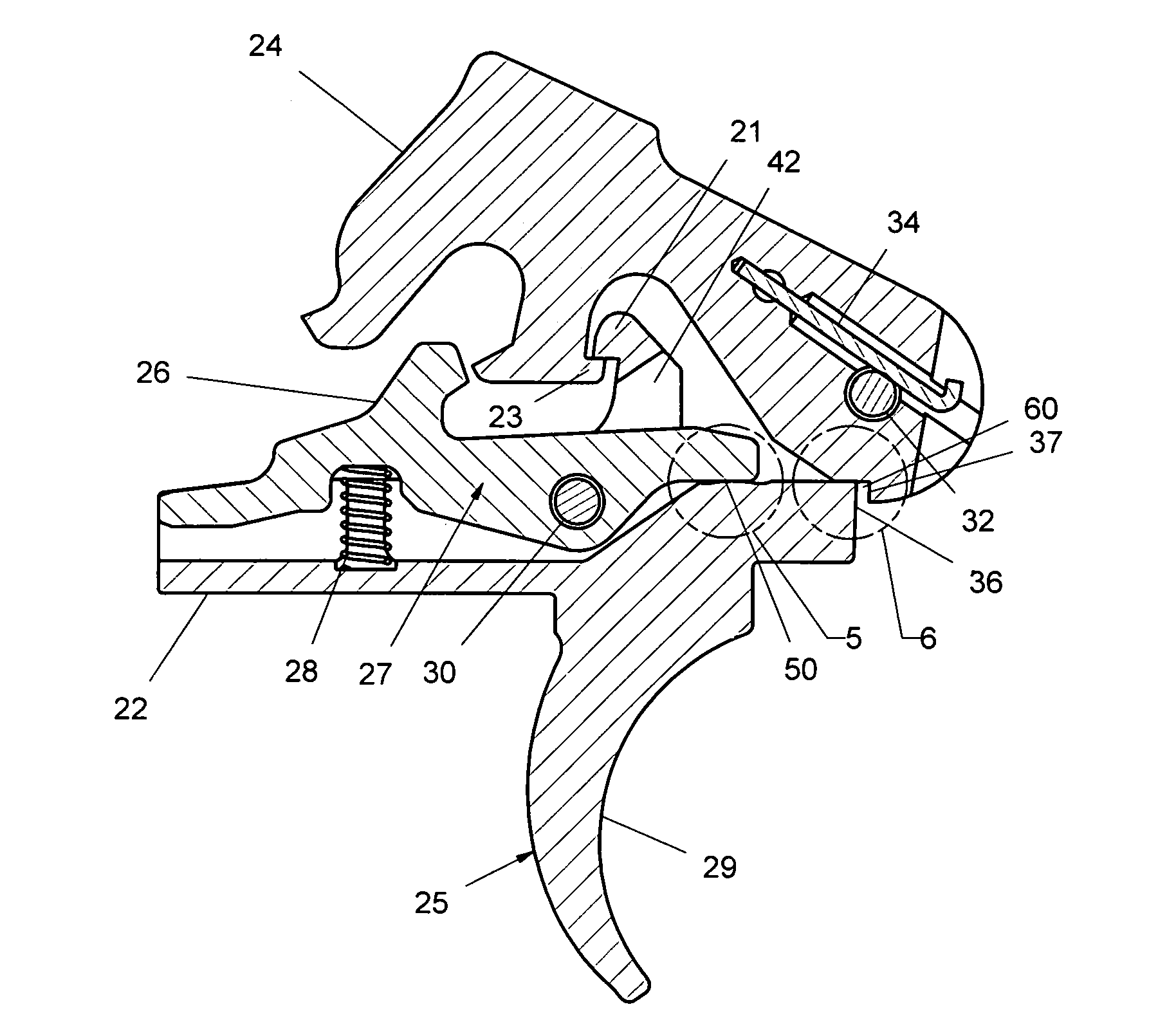
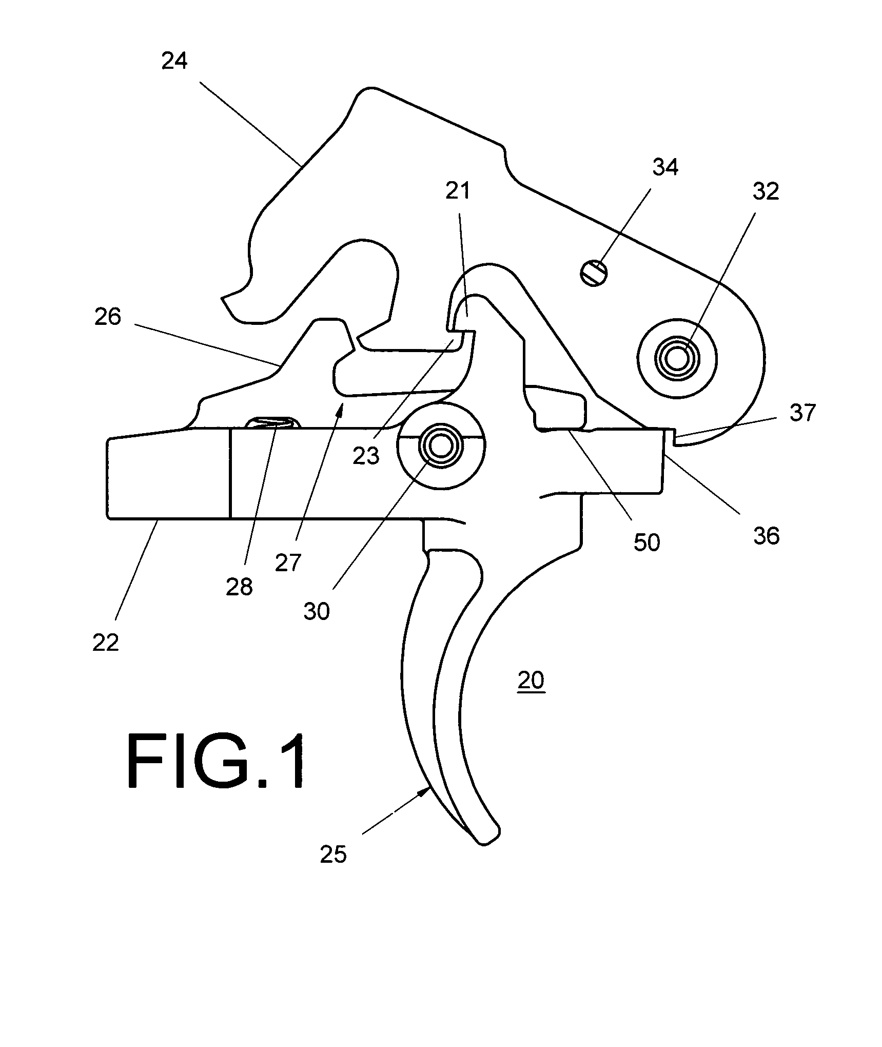
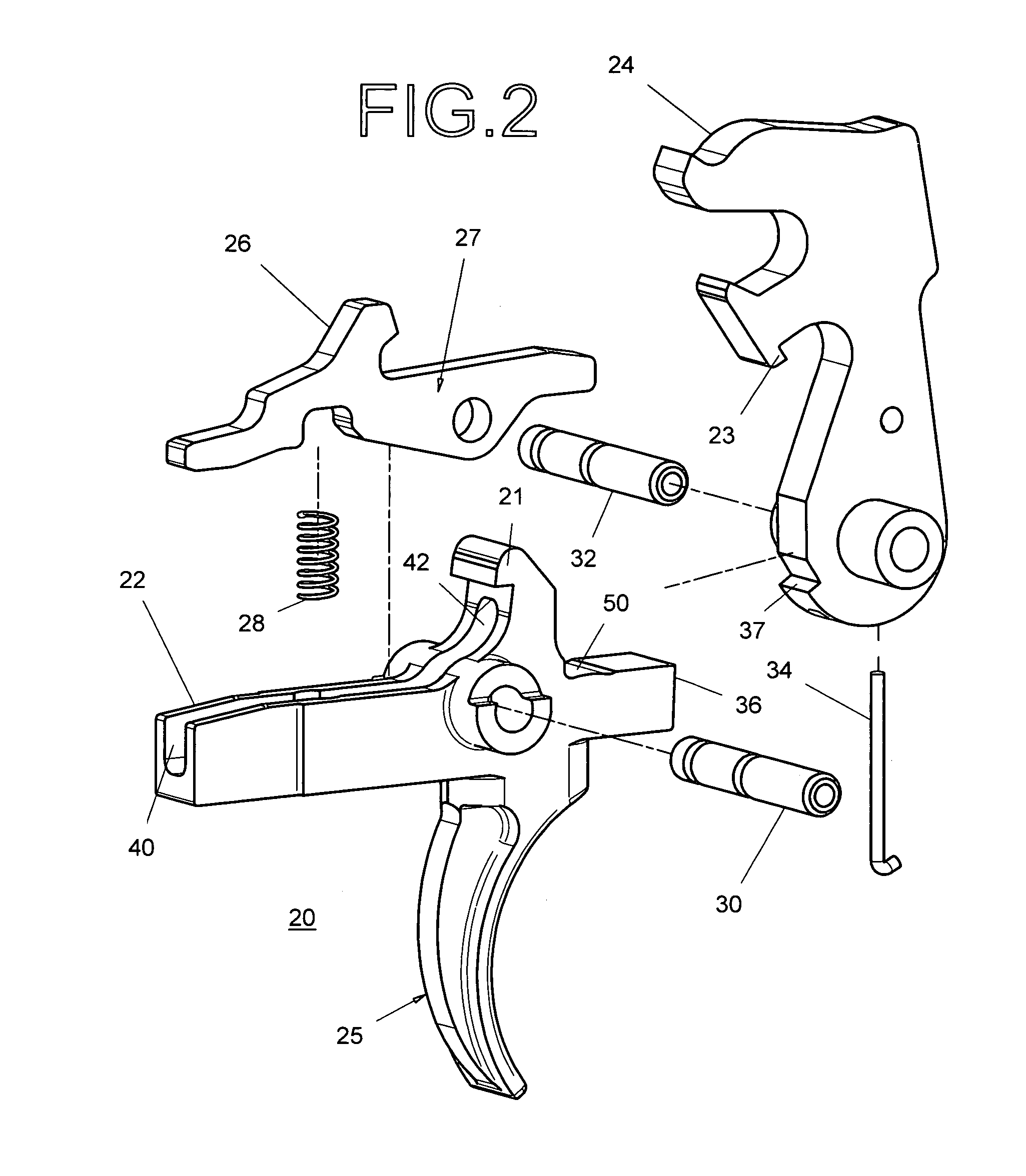
[0036]Turning now to the drawings in which like reference characters indicate corresponding elements throughout the several views, as used herein, the word “front” or “forward” corresponds to the end of the trigger assembly where the safety sear is located (i.e., to the right as shown in FIGS. 1, 2, 3, 4); “rear” or “rearward” or “back” corresponds to the direction opposite the end of the trigger assembly where the safety sear is located (i.e., to the left as shown in FIGS. 1, 2, 3, 4).

[0037]Attention is first directed to FIG. 1 which illustrates the trigger mechanism, generally designated 20 and FIG. 2 which is an exploded view of the trigger mechanism 20 of FIG. 1. It will be understood that trigger mechanism 20 is intended to be employed with any of the various M16 type firerms; however with minor modifications it could be more widely used for other firearms as well. M16 type firearms include the AR15 family of rifles, the M4 carbine family of rifles, the SR25 and AR10 larger cal...


PUM


Abstract

A two-stage trigger assembly for the M16 or AR15 weapon systems. The trigger assembly comprises a spring loaded hammer, trigger and disconnector. Calibrated springs are provided to facilitate the adjustment of the second stage trigger pull weight. No set screws adjustments are necessary and a secondary safety sear similar to the factory original fire control components has been incorporated to prevent the unintentional mechanical discharge of the firearm. Installation of the disclosed device is identical to the factory fire control group and requires no hand fitting.

Description

BACKGROUND OF THE INVENTION[0001]1. Field of Invention[0002]This application relates in general to two-stage trigger systems with improved safety and manufacturability features for semi-automatic weapons and specifically to the use of said trigger assembly on an AR-15 type rifle.[0003]2. Prior Art[0004]The trigger assembly of the proposed invention was designed to increase the control an individual shooter has over the timing of the host firearms discharge of a round and thereby effectively increase the accuracy potential of a shooter by minimizing mechanical distractions which hinder accurate gun fire. A smooth crisp trigger is essential if the user is to control when the firearm discharges. Precision shooters, be they military, law enforcement or civilian competitors require total control of the trigger mechanism to attain the maximum accuracy potential of their rifle. For military and law enforcement precision shooters control over the trigger mechanism is essential to the succes...

Claims


Application Information

Patent Timeline
Patent Type & Authority Patents(United States)
IPC IPC(8): F41A3/00
CPCF41A19/10
Inventor GEISSELE, WILLIAM H.
Owner WHG PROPERTIES
Why Eureka
Try Eureka