Direct thermal barcode printer

a barcode printer and thermal barcode technology, applied in the field of printers, can solve the problems of increased “down-time” or availability of the printer, complicated calibration or alignment of the print head with respect to the different print media types, and increased costs for customers

Active Publication Date: 2009-10-13
HAND HELD PRODS
View PDF31 Cites 43 Cited by
  • Summary
  • Abstract
  • Description
  • Claims
  • Application Information

AI Technical Summary

Benefits of technology

[0008]In particular, the media storage assembly is adapted to receive a quantity of a print media and position the print media for printing. The media storage assembly includes first and second support members that are positionable along an axis of the platen bracket and generally biased by springs towards a center of the platen bracket thereby securing the print media in the media storage assembly. First and second support members may lock in position after a desired amount of movement away from the center of the platen bracket thereby facilitating the installation and / or removal of the print media in the media storage assembly. Additionally, movement of the first and second support members may be synchronized such that when a support member is moved a distance from the center of the platen bracket, the other support member moves a corresponding distance in the opposing direction from the center of the platen bracket.
[0011]The print adjustment assembly, in cooperation with the carrier bracket, includes a shaft and one or more thumbwheels rotatably attached to the carrier bracket. Rotation of one thumbwheel urges the shaft longitudinally within an elongate opening of the carrier bracket. As the shaft contacts a surface of either shaft bracket without contacting a surface of the pivot bracket, the adapter plate is pivoted causing it to skew with respect to the roller. In one embodiment, two thumbwheels are included that are independently rotatable for precisely aligning the print head to the print media and the roller. In another embodiment, the thumbwheels are adapted for engaging correspondingly dimensioned holes in the platen bracket for releasably positioning the carrier assembly in the platen bracket.
[0012]The print head is rotatably mounted to the carrier bracket allowing repositioning of the print head towards and away from the roller. The pressure adjustment assembly includes a hub and at least one compression spring disposed between the hub and the carrier bracket. A ridge disposed on an outer surface of the hub interacts with at least one pointer on the carrier bracket such that rotation of the hub compresses or decompresses the at least one compression spring such that the print head applies more or less pressure, respectively, to the print media, thereby adjusting the printing pressure.

Problems solved by technology

In some prior art printers, calibration or alignment of the print head with respect to the different print media types is complicated and may require the printer to be returned to the factory or a service center.
This may result in additional costs to the customer as well as increased “down-time” or availability of the printer.

Method used


Image

  • Direct thermal barcode printer
  • Direct thermal barcode printer
  • Direct thermal barcode printer

Examples


Embodiment Construction

[0027]Embodiments of the presently disclosed direct thermal barcode printer will now be described in detail with reference to the drawings, in which like reference numerals designate identical or corresponding elements in each of the several views.

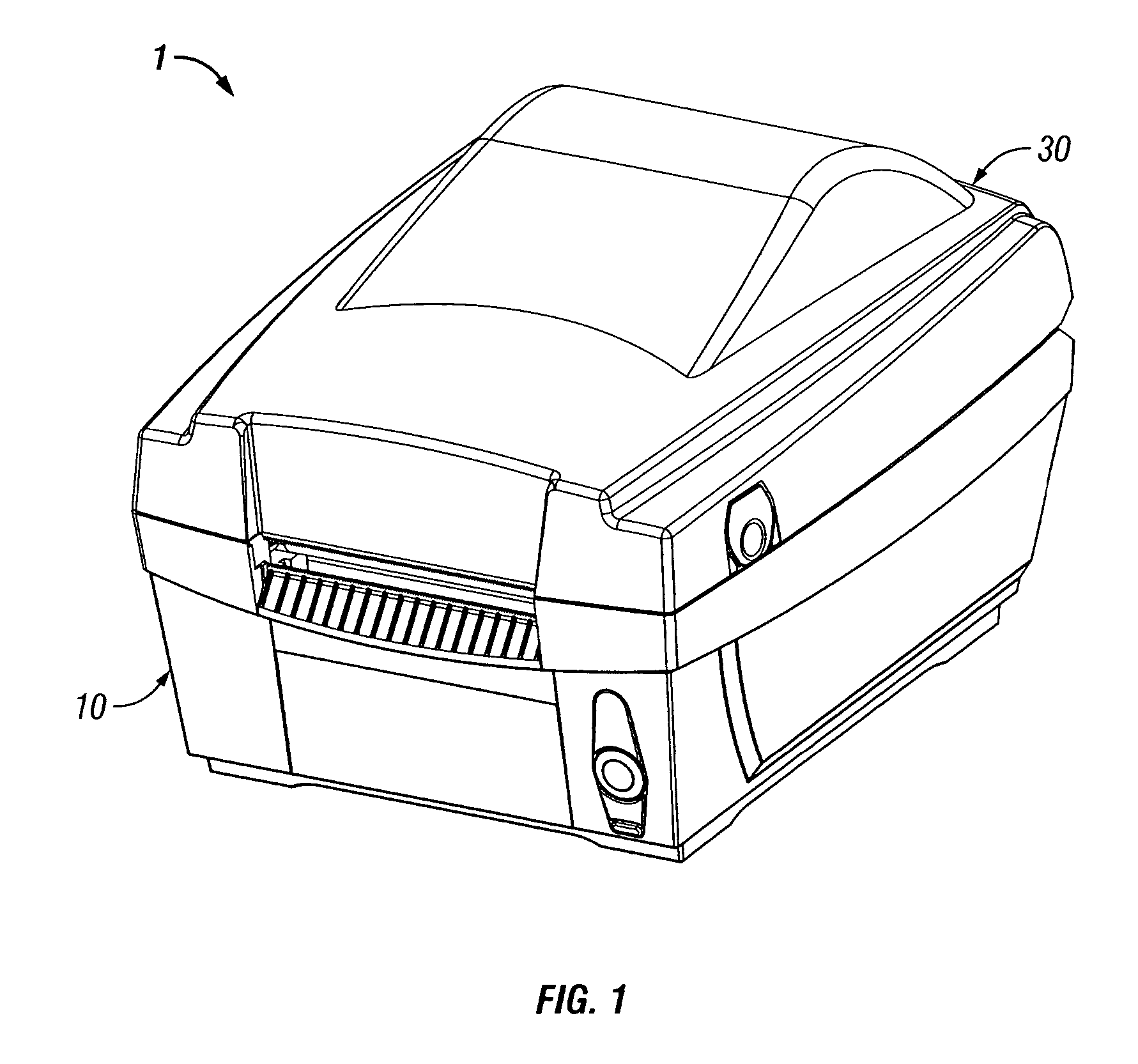
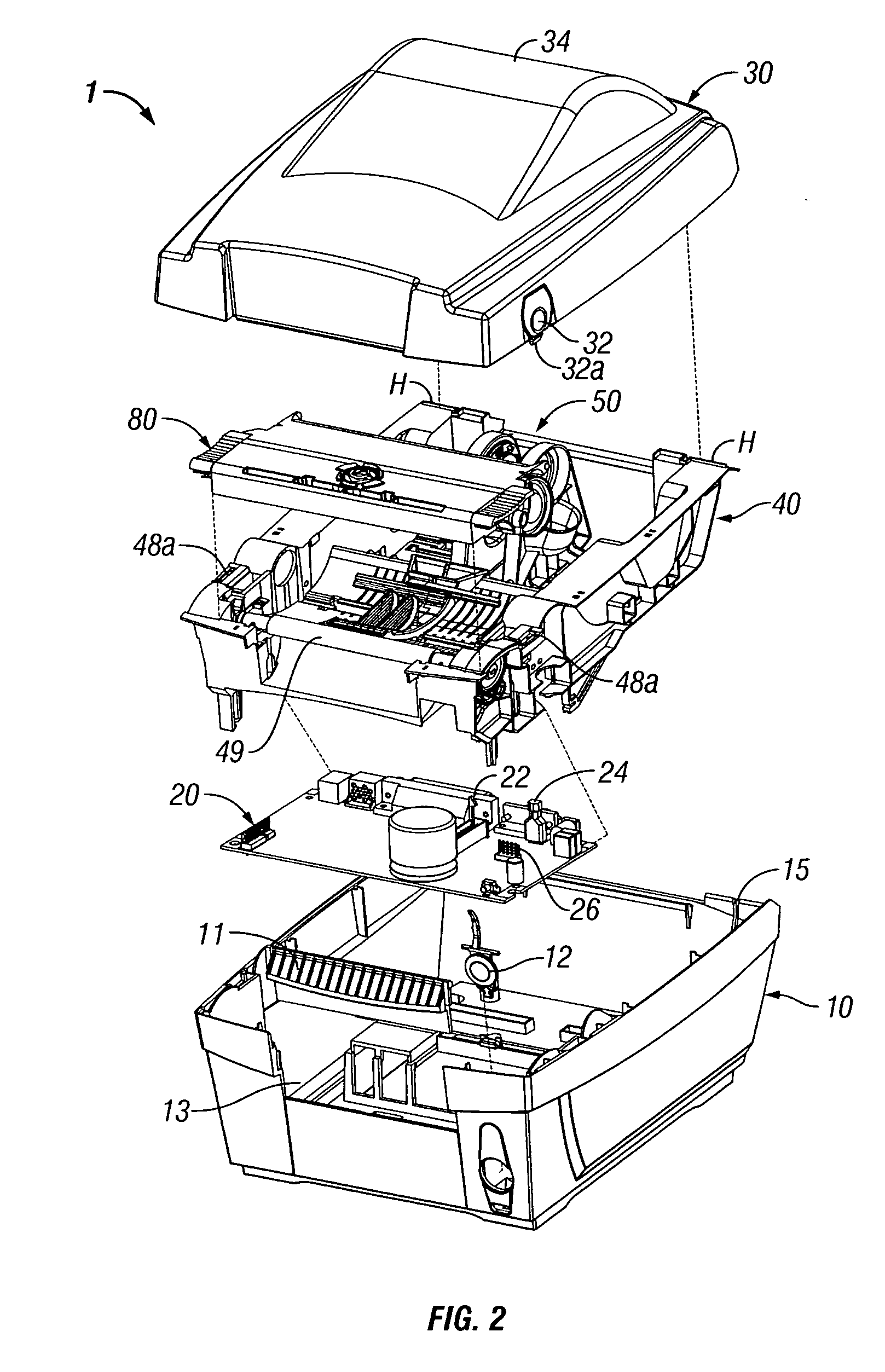
[0028]Referring initially to FIG. 1, the direct thermal barcode printer, shown generally as 1, includes a base 10 and a cover 30. Printer 1 is supplied with power from an electrical source (not shown). The electrical source of power may be AC or DC depending on the desired configuration of printer 1. A more detailed view of printer 1 is shown in FIG. 2. A front face of base 10 includes a fascia plate 11 that is adapted to fit within an opening 13 that is defined along the front face of base 10. A switch or a button 12 is positioned on the front face of base 10 and is in electrical communication with a printed circuit board 20 that is disposed within base 10. Button 12 is capable of controlling operations of printer 1 such as pause, resume,...


PUM

PropertyMeasurementUnit
diameteraaaaaaaaaa
diameteraaaaaaaaaa
distanceaaaaaaaaaa

Abstract

A direct thermal barcode printer including a print assembly is provided. The print assembly is movably positioned relative to a print media for adjusting printing characteristics of an attached print head.

Description

CROSS-REFERENCE TO RELATED APPLICATIONS[0001]This application is a continuation-in-part of U.S. patent application Ser. No. 11 / 103,105, filed on Apr. 11, 2005 now U.S. Pat. No. 7,131,778, the disclosure of which is hereby incorporated by reference herein in its entirety.BACKGROUND OF THE INVENTION[0002]1. Field of the Invention[0003]The present disclosure relates to printers in general and, more particularly, to a direct thermal barcode printer.[0004]2. Description of the Related Art[0005]The use of electronically controlled thermal printers has increased very rapidly over the last few years. In particular, the market for thermal label printers has shown significant improvement with users focusing on utilizing label printing, especially bar-code labeling, to improve capital asset management, inventory control or time and attendance reporting—or to meet corporate or industry mandated labeling requirements—such as automotive AIAG, electronic EIA, or retail UCC / UPC specifications. Labe...

Claims


Application Information

Patent Timeline
Patent Type & Authority Patents(United States)
IPC IPC(8): G06F3/12
CPCB41J2/32B41J3/4075B41J29/02B41J29/13B41J15/042B41J2202/31B65H16/06B65H2301/41342B65H2511/12B65H2511/14B65H2801/12B65H2220/04
Inventor TOBIN, DWAYNEBOUVERIE, WILLIAM M.COLONEL, KENNETHPLASSCHAERT, PAULWILSON, KIM
Owner HAND HELD PRODS
Why Eureka
Try Eureka