Wire harness fixing device

a technology of fixing device and wire harness, which is applied in the direction of coupling device connection, insulated conductor, domestic cooling apparatus, etc., can solve the problems of difficult assembly and installation of conventional wire harness fixing device, easy leakage of foam insulation material to the outside of the inner liner, etc., and achieve the effect of effective prevention of leakag

Inactive Publication Date: 2009-10-13
SAMSUNG GWANGJU ELECTRONICS CO LTD
View PDF11 Cites 3 Cited by
  • Summary
  • Abstract
  • Description
  • Claims
  • Application Information

AI Technical Summary

Benefits of technology

[0007]The present invention has been made in view of the above and other problems, and an aspect of the present invention is to provide a wire harness fixing device designed to enable convenient installation thereof within an inner liner of a refrigerator while effectively preventing leakage of the foam insulation material between the inner liner and an outer liner of the refrigerator.
[0010]The cover may extend radially at a predetermined angle from an outer surface of the interior part towards the insert part, and be tapered such that, as the cover approaches from the interior part to the insert part, a distance between an outer periphery of the cover and the outer surface of the housing is gradually increased.
[0019]The wire harness fixing device may further comprise a sealing member on an inner surface of each hinge coupler at the withdrawal port side to enhance closing force between the withdrawal port and the wire harness.

Problems solved by technology

However, with such a conventional wire harness fixing device, the foam insulation material can easily leak to the outside of the inner liner through gaps between the housing and the housing cover or through gaps between the shielding portion and the inner liner, which are separately provided, when filling the space between the inner and outer liners with the foam insulation material.
As such, conventional wire harness fixing devices are difficult to assemble and install due to the adhesives and the resilient holder.

Method used


Image

  • Wire harness fixing device
  • Wire harness fixing device
  • Wire harness fixing device

Examples


Embodiment Construction

[0035]Reference will now be made in detail to the embodiments of the present invention, examples of which are illustrated in the accompanying drawings. The embodiments are described below to explain the present invention by referring to the accompanying drawings.

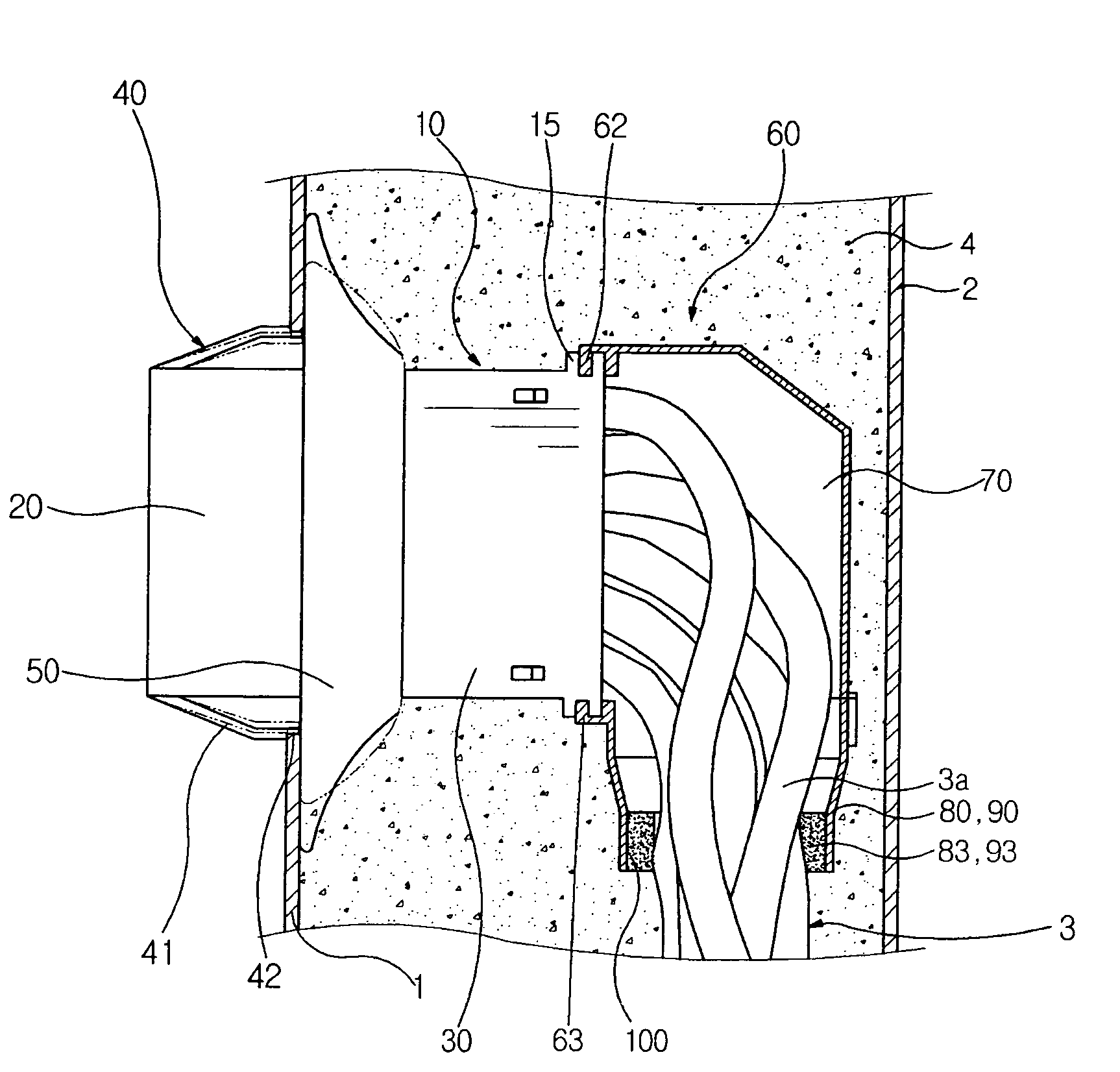
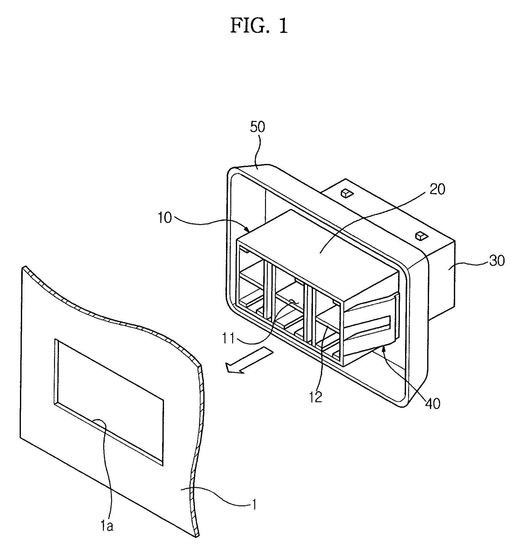
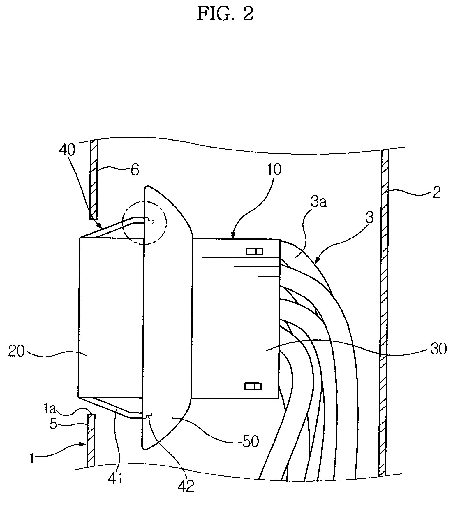
[0036]A wire harness fixing device according to one embodiment of the present invention serves to fix a wire harness 3 (FIG. 2) positioned in a space between an inner liner 1 and an outer liner 2 of a refrigerator to the inner liner 1. As shown in FIGS. 1 to 7, the wire harness fixing device comprises a parallelepiped housing 10, which can be produced by injected molding, and includes a through hole 11 (FIG. 1) formed therein to receive a plurality of electric lines or wires 3a.

[0037]The through hole 11 is formed with a plurality of partition plates 12 by which the electric lines 3a are divided, and then received in the housing 10. The electric lines 3a extend though the space between the inner liner 1 and the outer liner 2...


PUM


Abstract

A wire harness fixing device designed to enable convenient installation thereof within an inner liner of a refrigerator while effectively preventing leakage of a foam insulation material filled between the inner liner and an outer liner of the refrigerator. The wire harness fixing device includes a housing including an insert part provided at one end of the housing and inserted through a fixing hole formed in the inner liner, and an interior part positioned at the other end within the inner liner. A latch is provided on the insert part that engages an outer surface of the inner liner at the fixing hole when the insert part is inserted into the fixing hole, and a cover of a flexible material integrally formed to the housing at the interior part side to cover the fixing hole, the cover being subjected to elastic deformation to closely contact an inner surface of the inner liner at the fixing hole side when the latch is latched to and supported by the inner liner.

Description

CROSS-REFERENCE TO RELATED APPLICATION[0001]This application claims priority under 35 U.S.C. §119 to Korean Patent Application Nos. 2005-27901 and 2005-71900, filed on Apr. 4, 2005 and Aug. 5, 2005, respectively, in the Korean Intellectual Property Office, the disclosure of which is incorporated herein by reference.FIELD OF THE INVENTION[0002]The present invention relates to a wire harness fixing device, and, more particularly, to a wire harness fixing device designed to enable convenient installation thereof within an inner liner of a refrigerator while effectively preventing leakage of a foam insulation material filled between the inner liner and an outer liner of the refrigerator.BACKGROUND OF THE INVENTION[0003]Generally, a refrigerator includes a foam insulation material filled to form an insulation layer between an inner liner constituting an inner wall of a storage room and an outer liner constituting an outer wall of a body, and a wire harness provided through the insulation...

Claims


Application Information

Patent Timeline
Patent Type & Authority Patents(United States)
IPC IPC(8): H02G3/08H01G9/02H01H9/02H01R13/40
CPCF25D23/064H01R13/743F25D2400/40H01R13/5205H01R13/5829H01R13/506Y10S248/906
Inventor KIM, YOUNG RYOLNAM, SEUNG WEON
Owner SAMSUNG GWANGJU ELECTRONICS CO LTD
Why Eureka
Try Eureka