Gas exhausting device for injection mold

a gas exhausting device and injection mold technology, which is applied in the direction of valve operating means/releasing devices, functional valve types, mechanical devices, etc., can solve the problems of air being discharged in the cavity, affecting the quality of injection mold products, etc., to achieve smooth gas discharge, prevent the leakage of molten resin, and facilitate the effect of closing

Inactive Publication Date: 2018-10-04
KIM CHEON SEOP
View PDF0 Cites 2 Cited by
  • Summary
  • Abstract
  • Description
  • Claims
  • Application Information

AI Technical Summary

Benefits of technology

[0022]According to the present invention having the above-described configuration, two compression coil springs having a spring constant different from each other are used, so that the poppet is easily closed by the injection pressure without being closed by the vacuum pressure for sucking the gas. Accordingly, it is possible to smoothly discharge the gas while effectively preventing the leakage of the molten resin.
[0023]In addition, when the injection-molding process is completed, the poppet can be smoothly opened as the first compression coil spring having a larger spring constant is restored.
[0024]In addition, the durability and lifespan of components can be improved by dispersing fatigue of the two compression coil springs caused by the repeated compression and extension.

Problems solved by technology

However, the air accommodated in the cavity may not be completely discharged as the molten resin is rapidly injected into the cavity.
If an injection-molded product is manufactured with the molten resin, which is cooled while being mixed with the air remaining in the cavity, the injection-molded product may have various defects including air bubbles and porosity.
Therefore, one of the major problems to be solved upon the manufacture of the injection-molded article is to discharge the air inside the cavity and the gas generated during the injection-molding.
According to the related art, since the head portion of the opening-closing member opens and closes a cavity-side inlet of the first hollow while being elastically supported by one elastic member, if an elastic force of the elastic member is decreased due to repeated opening and closing, a distance between the head portion and the cavity-side inlet of the first hollow is decreased, so that the gas remaining in the cavity of the injection mold cannot be smoothly sucked and discharged.
If the elastic force of the elastic member is decreased, the head portion is not completely returned to a state that the first hollow is completely opened, so that the gas is not smoothly discharged during the next injection-molding process.
However, if the elastic modulus of both the first elastic member and the second elastic member is decreased, the descending core may not smoothly return.

Method used


Image

  • Gas exhausting device for injection mold
  • Gas exhausting device for injection mold
  • Gas exhausting device for injection mold

Examples


embodiment

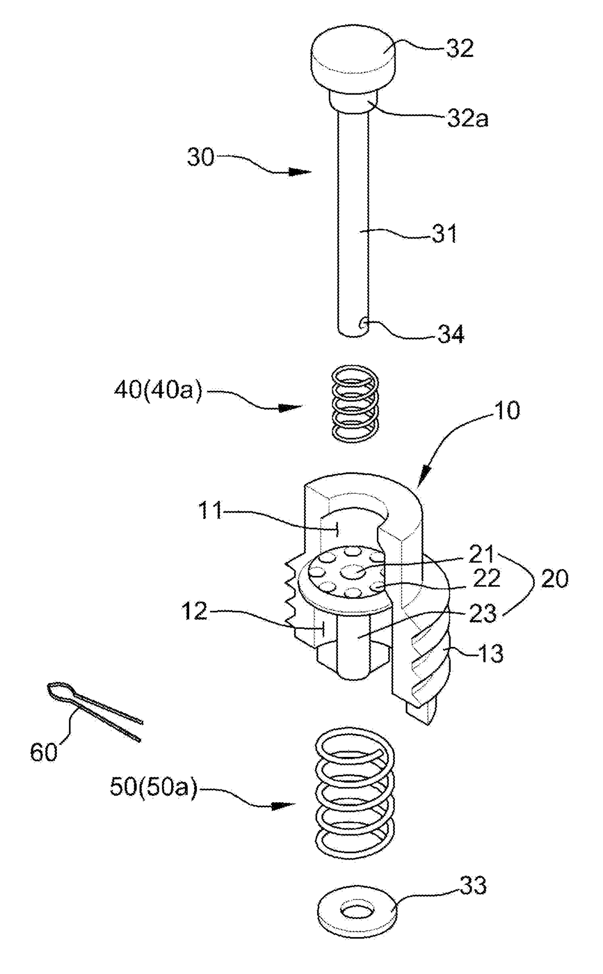
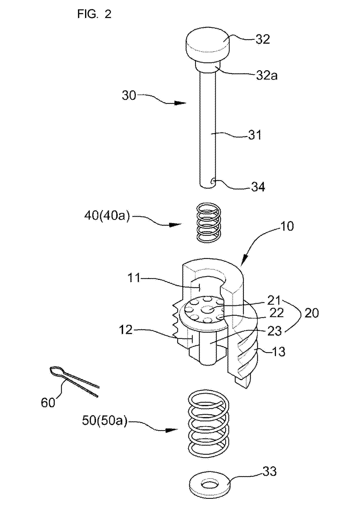
[0097]In the present invention, if the spring constant of the first compression coil spring 40a is 100, the spring constant of the second compression coil spring 50a may be 50 or more and 70 or less.

[0098]When the first compression coil spring 40a and the second compression coil spring 50a are mounted in a compressed state, if the compressed length of the first compression coil spring 40a is 1, the compressed length of the second compression coil spring 50a may be relatively 3 to 4.

[0099]In addition, when the poppet 30 is completely closed, the compressed length of the first compression coil spring 40a may be approximately 2 to 3. If the compressed length of the first compression coil spring 40a is 2, the compressed length of the second compression coil spring 50a may be relatively 2 to 3.

[0100]In addition, assuming the compressive force acting on the head 32 is 100 in the case where only the first compression coil spring 40a is mounted and the poppet 30 is completely closed, the co...


PUM

PropertyMeasurementUnit
diameteraaaaaaaaaa
compressed lengthaaaaaaaaaa
shapeaaaaaaaaaa

Abstract

Provided is a gas exhausting device for an injection mold. The gas exhausting device includes: an introduction socket; an introduction holder provided at an inner portion of the introduction socket in a transverse direction; a poppet including a body, a head, and a support ring; a first elastic member interposed between the head of the poppet and the introduction holder to elastically support one end of the poppet; and a second elastic member interposed between the support ring of the poppet and the introduction holder to elastically support an opposite end of the poppet, wherein the first elastic member includes a first compression coil spring installed in a compressed state, the second elastic member includes a second compression coil spring installed in a compressed state, and a spring constant of the first compression coil spring is larger than a spring constant of the second compression coil spring.

Description

CROSS REFERENCES[0001]Applicant claims foreign priority under Paris Convention to Korean Patent Application No. 10-2017-0043812, filed 4 Apr. 2017, with the Korean Intellectual Property Office, where the entire contents are incorporated herein by reference.BACKGROUND[0002]The present invention relates to a gas exhausting device for an injection mold, and more particularly, to a gas exhausting device for an injection mold, capable of smoothly sucking and discharging a gas remaining in a cavity of the injection mold during an injection-molding process.[0003]In general, when a mold is used to manufacture an injection-molded article, a molten resin is injected into a cavity defined by an upper mold and a lower mold coupled with the upper mold. At this time, a soluble resin such as a plastic is widely used as the molten resin.[0004]However, the air accommodated in the cavity may not be completely discharged as the molten resin is rapidly injected into the cavity. If an injection-molded p...

Claims


Application Information

Patent Timeline
Patent Type & Authority Applications(United States)
IPC IPC(8): B29C45/34F16K17/04F16K31/122
CPCB29C45/34F16K31/1221F16K17/044
Inventor KIM, CHEON SEOP
Owner KIM CHEON SEOP
Why Eureka
Try Eureka