
DMA controller connected to master and slave device wherein a rank is used for judging data transfer permissibility

a data transfer and master device technology, applied in the field of dma controllers, can solve the problems of data transfer stopping, data loss or destruction of important data stored in a device to which the data has been wrongly transferred, and the dma controller may fail to recognize the correct address and transfer data to the wrong address, etc., to save the processing load.

Inactive Publication Date: 2008-11-25
PANASONIC CORP
View PDF4 Cites 4 Cited by
  • Summary
  • Abstract
  • Description
  • Claims
  • Application Information

AI Technical Summary

Benefits of technology

"The present invention provides a DMA controller that can perform data transfer between devices while effectively preventing leakage of secret information. The DMA controller includes a data transfer control unit connected to a master device and multiple slave devices. The data transfer control unit includes a rank storage unit for storing the rank of each slave device, a comparison unit for comparing the rank of the master device with the rank of the slave devices, and a transfer permissibility judgment unit for determining whether to permit or prohibit the data transfer based on the results of the comparison. The data transfer control method involves sending the rank of the master device to the slave device to request access, and judging whether to permit or prohibit the data transfer based on the rank of the slave device. This prevents unauthorized data transfer between data storage areas and ensures efficient data transfer control."

Problems solved by technology

This being so, if noise or the like occurs in address signals, the DMA controller may fail to recognize correct addresses and transfer data to wrong addresses.
As a result, important data stored in a device to which the data has been wrongly transferred may be lost or destroyed by overwriting.
According to this technique, when an error occurs in the address-related data due to noise or the like, the data transfer is stopped.
In cases where the level of secrecy differs between devices, however, the above conventional technique has the following problem.

Method used


Image

  • DMA controller connected to master and slave device wherein a rank is used for judging data transfer permissibility
  • DMA controller connected to master and slave device wherein a rank is used for judging data transfer permissibility
  • DMA controller connected to master and slave device wherein a rank is used for judging data transfer permissibility

Examples


first embodiment

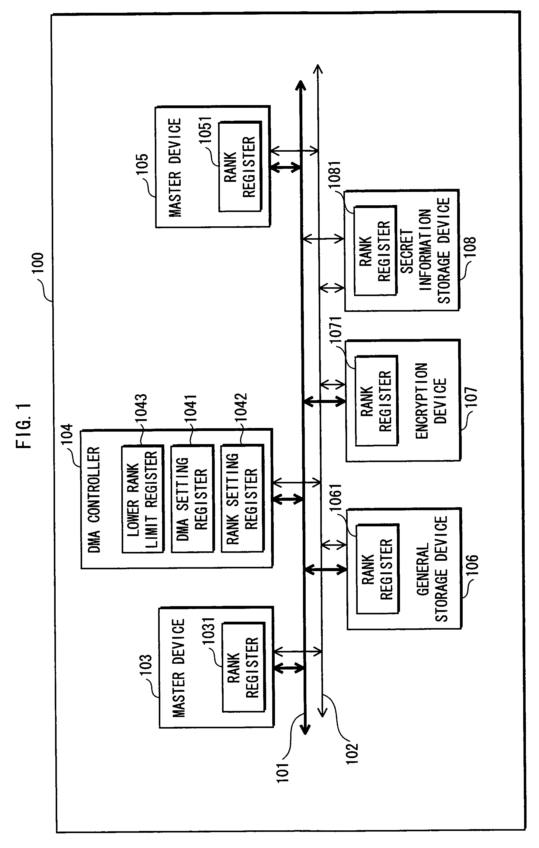
[0092]FIG. 1 is a functional block diagram showing a construction of a secret information processing apparatus 100 to which a first embodiment of the present invention relates.

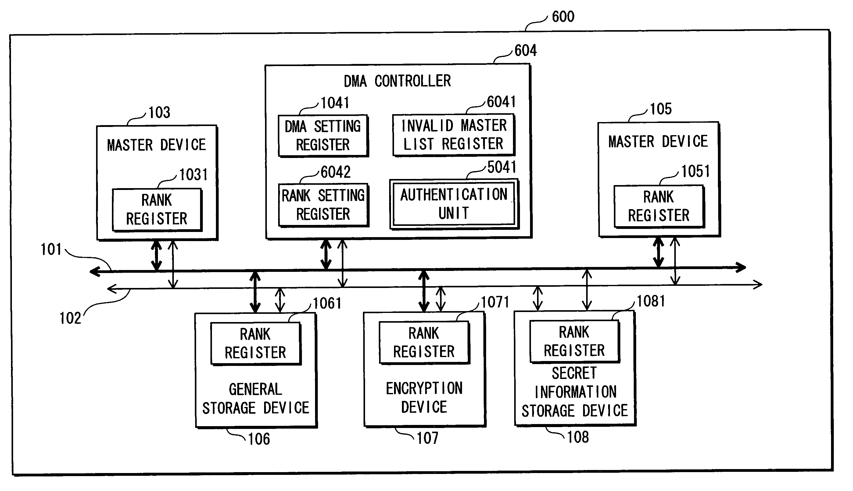
[0093]As shown in the drawing, the secret information processing apparatus 100 is roughly made up of devices that include a data / address bus 101, a rank bus 102, a master device 103, a DMA controller 104, a master device 105, a general storage device 106, an encryption device 107, and a secret information storage device 108.

[0094]Note here that the secret information processing apparatus 100 may be connected to an external device via an external interface.

[0095]The data / address bus 101 is used for transferring data and addresses.

[0096]The rank bus 102 is used for transferring ranks.

[0097]A rank referred to here is information which is used when judging whether access to a device in the secret information processing apparatus 100 is permitted or not, that is, whether a data transfer to or from the device is per...

second embodiment

[0124]FIG. 3 is a functional block diagram showing a construction of a secret information processing apparatus 200 to which a second embodiment of the present invention relates.

[0125]As shown in the drawing, the secret information processing apparatus 200 is roughly made up of devices that include the data / address bus 101, the rank bus 102, the master device 103, a DMA controller 204, the master device 105, the general storage device 106, the encryption device 107, and the secret information storage device 108.

[0126]In FIG. 3, construction elements which are the same as those in the secret information processing apparatus 100 in the first embodiment have been given the same reference numerals and their explanation has been omitted. The following describes the differences from the first embodiment.

[0127]Note here that the secret information processing apparatus 200 may be connected to an external device via an external interface.

[0128]The DMA controller 204 includes the DMA setting r...

third embodiment

[0145]FIG. 7 is a functional block diagram showing a construction of a secret information processing apparatus 300 to which a third embodiment of the present invention relates.

[0146]As shown in the drawing, the secret information processing apparatus 300 is roughly made up of devices that include the data / address bus 101, the rank bus 102, the master device 103, a DMA controller 304, the master device 105, the general storage device 106, the encryption device 107, and the secret information storage device 108.

[0147]In FIG. 7, construction elements which are the same as those in the secret information processing apparatus 100 in the first embodiment have been given the same reference numerals and their explanation has been omitted. The following describes the differences from the first embodiment.

[0148]Note here that the secret information processing apparatus 300 may be connected to an external device via an external interface.

[0149]The DMA controller 304 includes the DMA setting re...


PUM


Abstract

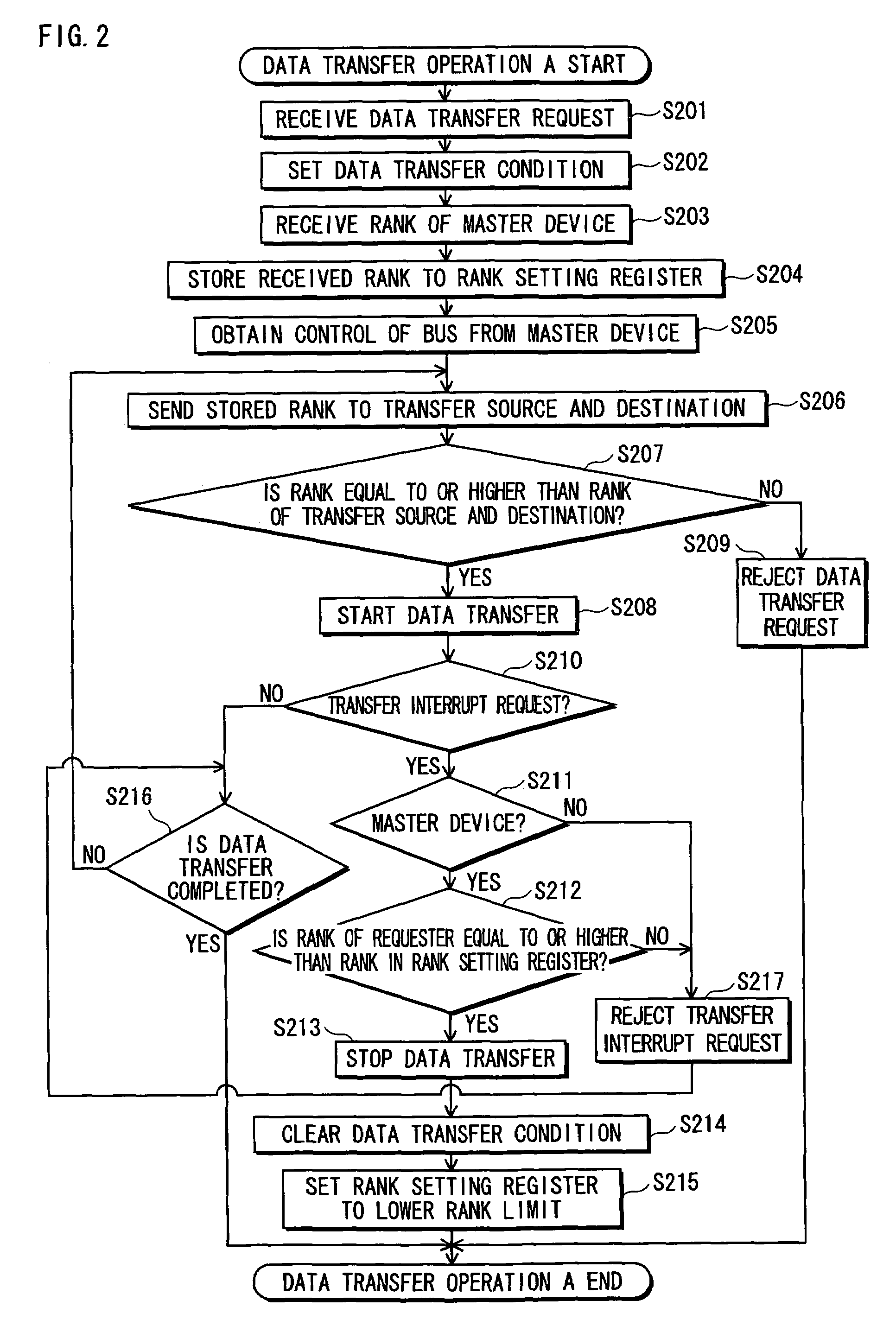
A DMA controller is connected by a bus to a plurality of master devices and a plurality of slave devices, and performs a data transfer between slave devices which are specified as a source and a destination of the data transfer by a transfer condition received from any of the plurality of master devices. Each of the plurality of master devices and the plurality of slave devices has a rank used for judging data transfer permissibility. The DMA controller enables the data transfer if the data transfer is judged to be permitted as a result of a comparison between a rank of the master device and a rank of any of the specified slave devices, and disables the data transfer if the data transfer is judged to be prohibited.

Description

[0001]This application is based on an application No. 2005-142570 filed in Japan, the contents of which are hereby incorporated by reference.BACKGROUND OF THE INVENTION[0002]1. Field of the Invention[0003]The present invention relates to data transfer control techniques for ensuring security when performing data transfers between devices using a DMA (Direct Memory Access) controller in a secret information processing apparatus.[0004]2. Related Art[0005]A DMA controller performs data transfers between devices, instead of a CPU. The CPU requests the DMA controller to perform a data transfer of a heavy load. This enables the CPU to execute other tasks while the DMA controller is performing the data transfer.[0006]The DMA controller performs a data transfer based on source and destination addresses given from the CPU. This being so, if noise or the like occurs in address signals, the DMA controller may fail to recognize correct addresses and transfer data to wrong addresses. As a result...

Claims


Application Information

Patent Timeline
Patent Type & Authority Patents(United States)
IPC IPC(8): G06F13/28G06F21/60G06F21/62G06F21/85
CPCG06F13/28
Inventor TORISAKI, YUISHIFUJIWARA, MAKOTONEMOTO, YUSUKE
Owner PANASONIC CORP
Learn More