Blower mounting apparatus

a technology for mounting apparatuses and blowers, which is applied in the direction of cleaning equipments, tractors, turf growing, etc., can solve the problems of obstructing the normal use of equipment and adding weigh

Active Publication Date: 2009-10-20
WOODCOCK JAMES +1
View PDF8 Cites 10 Cited by
  • Summary
  • Abstract
  • Description
  • Claims
  • Application Information

AI Technical Summary

Benefits of technology

[0006]The present invention is a blower mounting apparatus for conveniently mounting a street blower to the front of a zero-turn riding mower. The mounting apparatus suspends the blower above the ground and does not interfere with the turning ability of the mower. The blower mounting apparatus comprises a main support beam that extends across the front of the mower frame and rests on top of the frame and behind the front castor swivel wheels. The main beam preferably includes a securing mechanism that engages the left and right angled extensions of the mower frame to keep the mounting apparatus from sliding forward, backward, or to the sides. On top of the main support beam is a central eyebolt for anchoring a chain that holds the blower such that the wheels of the blower are preferably all suspended above the ground. At least two (2) lower support arms are attached to the main beam, each of which preferably comprises a substantially vertical support and a longer substantially horizontal support. At one end of the horizontal support is a cradle designed to support the axle or rear frame of the blower.

Problems solved by technology

A problem with these presently used hitches is that either the adapters must be removed from the equipment when the blower is not being used, a time-consuming and inconvenient process, or the adapters are left bolted to the equipment, resulting in added weight as well as obstructing the normal use of the equipment.

Method used


Image

  • Blower mounting apparatus
  • Blower mounting apparatus
  • Blower mounting apparatus

Examples


Embodiment Construction

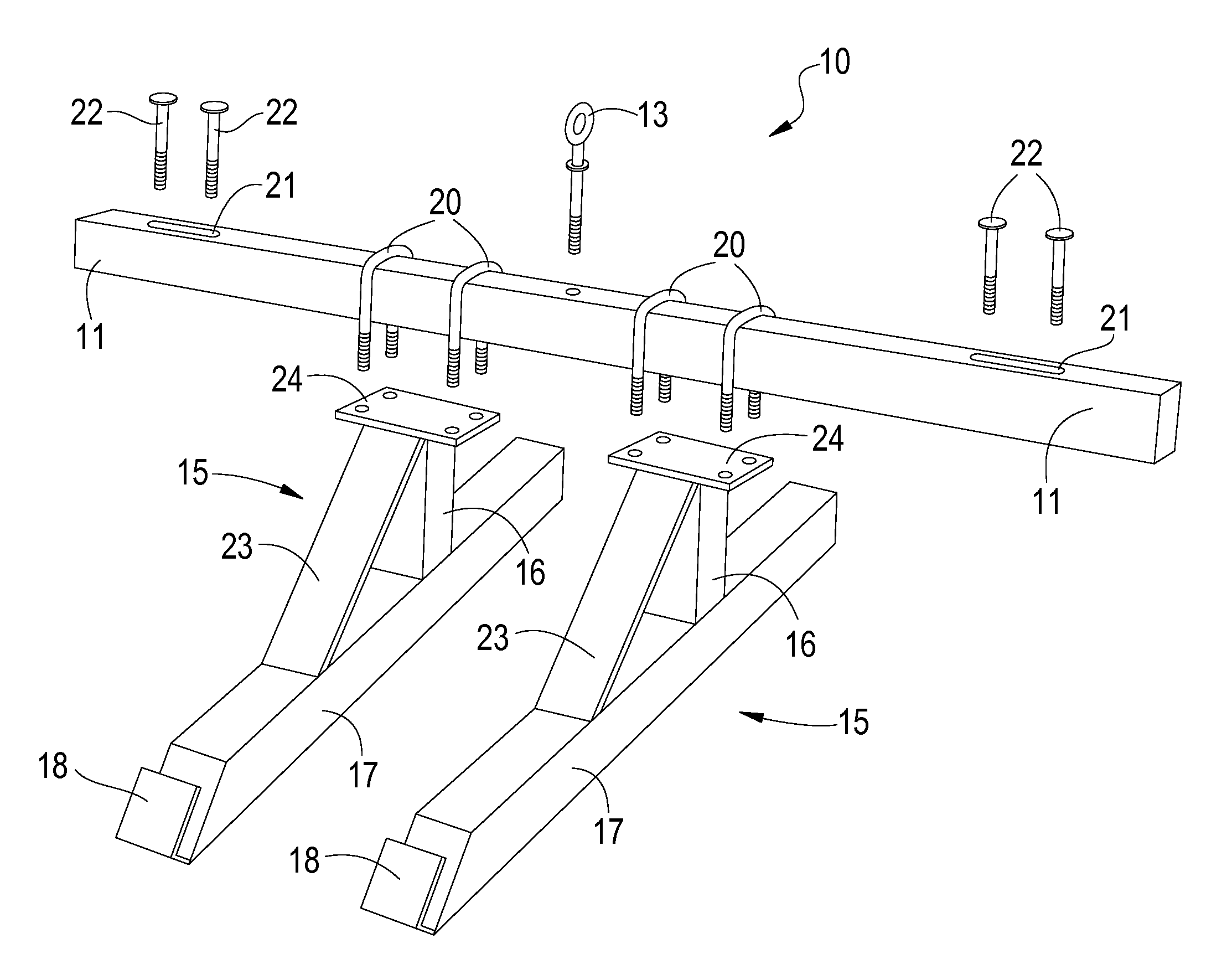
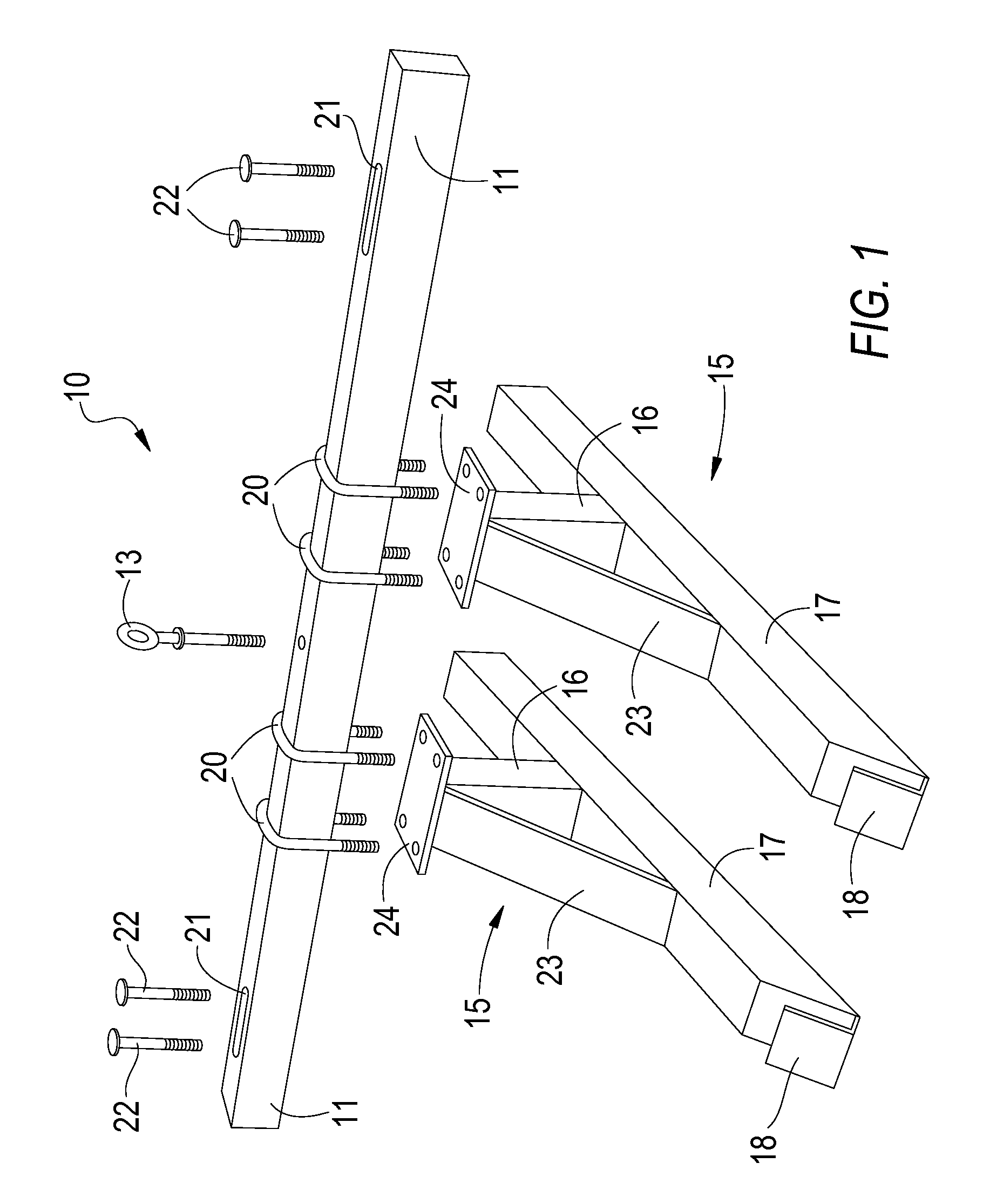
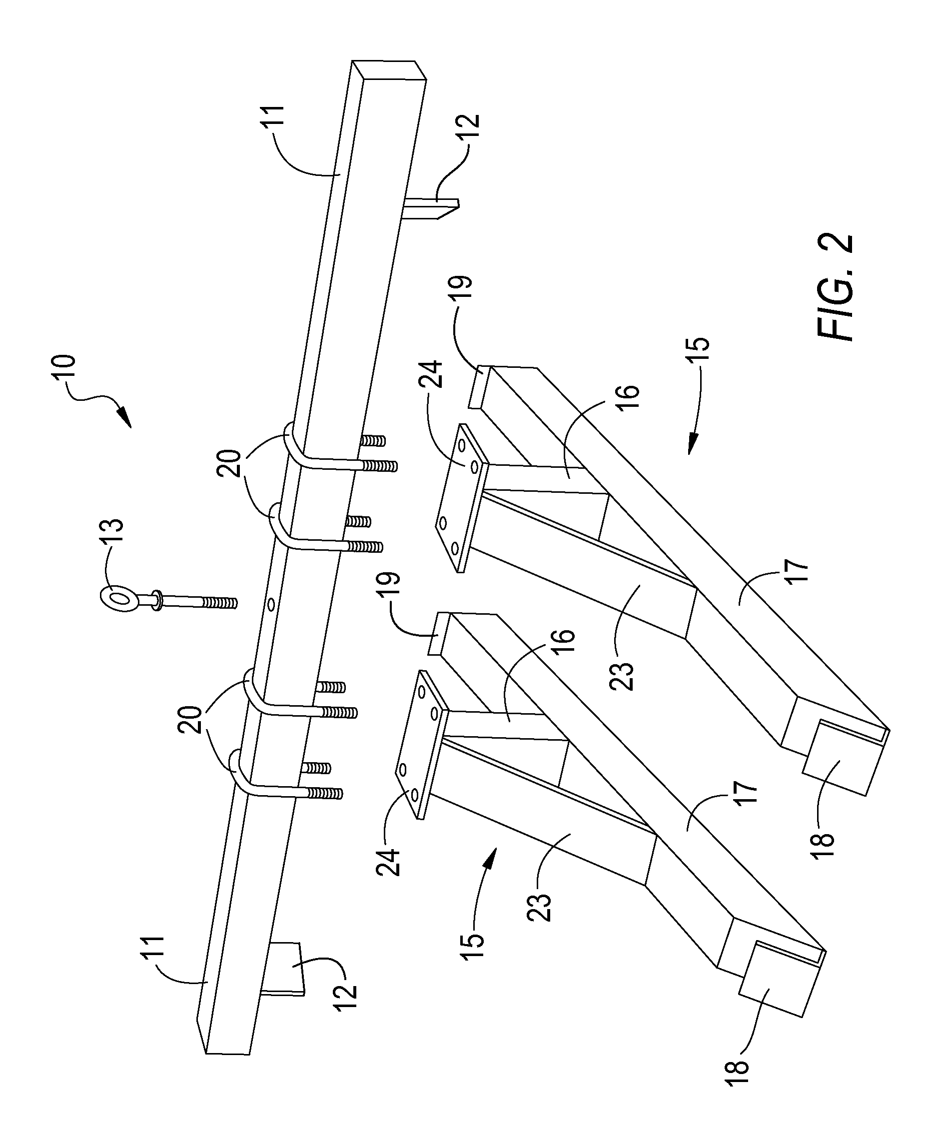
[0010]The present invention is a blower mounting apparatus 10 for mounting a street blower 25 to the front of a zero-turn riding mower 30. The mounting apparatus 10 suspends the blower above the ground and does not interfere with the turning ability of the mower. No changes need to be made to the blower or mower to use the apparatus. The mounting apparatus will fit a number of different blower and mower combinations.

[0011]In the preferred embodiment shown in FIGS. 1 and 3, the blower mounting apparatus 10 comprises a main support beam 11 made of tubular metal that extends across the front of the mower frame 40 and rests on top of the frame 40 and behind the front castor swivel wheels 41, thereby preventing the mounting apparatus 10 from sliding forward. The main beam 11 supports the majority of the blower's 25 weight as well as centers the blower 25 on the mower 30. On top of the main support beam 11 is a central eyebolt 13 for anchoring a chain or wire 14 that holds the blower 25 s...


PUM


Abstract

An apparatus for mounting a street blower to the front end of a zero-turn riding mower. The mounting apparatus comprises a main support beam that extends across the front of the mower frame and rests on top of the frame. The main beam preferably includes a securing mechanism that engages the left and right angled extensions of the mower frame to keep the mounting apparatus from sliding forward, backward, or to the sides. On top of the main support beam is a central eyebolt for anchoring a chain that holds the blower such that the wheels of the blower are preferably all suspended above the ground. At least two lower support arms are attached to the main beam, each of which comprises a vertical support and a horizontal support. At one end of the horizontal support is a cradle designed to support the axle or rear frame of the blower.

Description

RELATED PATENT APPLICATION[0001]The present application claims priority to U.S. Provisional Patent Application No. 60 / 642,411, filed Jan. 7, 2005, incorporated herein by reference.FIELD OF THE INVENTION[0002]The present invention is related to grounds care equipment, and more particularly, to an apparatus for mounting a street blower to a riding mower.BACKGROUND OF THE INVENTION[0003]A street blower (a.k.a. roll blower, push blower, or parking lot blower) is a gasoline powered air blower used to blow leaves and other debris from roads, parking lots, sidewalks, lawns, etc. These blowers are significantly more powerful than backpack and handheld blowers and are typically used by commercial grounds care businesses. Because of the size and weight of street blowers, they are too heavy to be carried and are thus mounted on wheels to allow workers to operate them.[0004]To improve the efficient use of street blowers, hitches have been developed for mounting the blowers to riding equipment, ...

Claims


Application Information

Patent Timeline
Patent Type & Authority Patents(United States)
IPC IPC(8): E01H1/02
CPCA01G1/125B62D49/065B62D49/04A01G20/47
Inventor WOODCOCK, JAMESBELCHER, JASON
Owner WOODCOCK JAMES
Why Eureka
Try Eureka