Dual-axis hinge for a portable electronic device

a dual-axis, electronic device technology, applied in the direction of portable computers, wing accessories, instruments, etc., can solve the problems of insufficient use of conventional hinges that pivot the cover in a single axis, and achieve the effect of more applicability

Inactive Publication Date: 2009-10-20
SHIN ZU SHING
View PDF4 Cites 0 Cited by
  • Summary
  • Abstract
  • Description
  • Claims
  • Application Information

AI Technical Summary

Benefits of technology

[0007]The main objective of the present invention is to provide a dual-axis hinge for a portable electronic device and that allows a cover of the portable electronic device to pivot relative to a base in two axes in different directions. Such that the dual-axis hinge provides more applicability when use in the portable electronic device.
[0013]With such an arrangement, the cover connected with the connecting leaf may pivot relative to the base in the first axis and the second axis and is then held at a desired position. Therefore, the dual-axis hinge allows the portable electronic device to make more motivation and contents to various applicability requirements.

Problems solved by technology

However, as more and more functions or programs in the portable electronic device have been developed, said conventional hinges that pivot the cover in a single axis gradually become inadequate to use.

Method used


Image

  • Dual-axis hinge for a portable electronic device
  • Dual-axis hinge for a portable electronic device
  • Dual-axis hinge for a portable electronic device

Examples


first embodiment

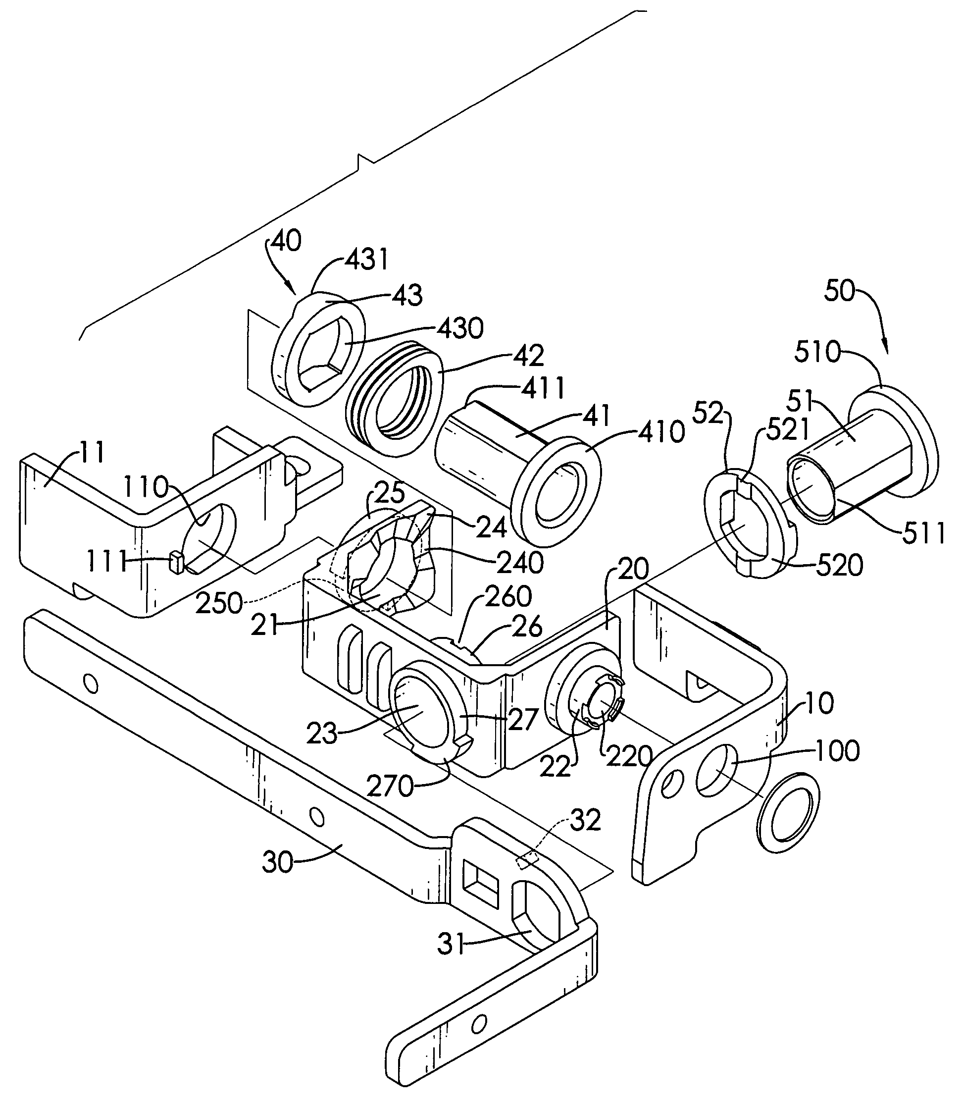
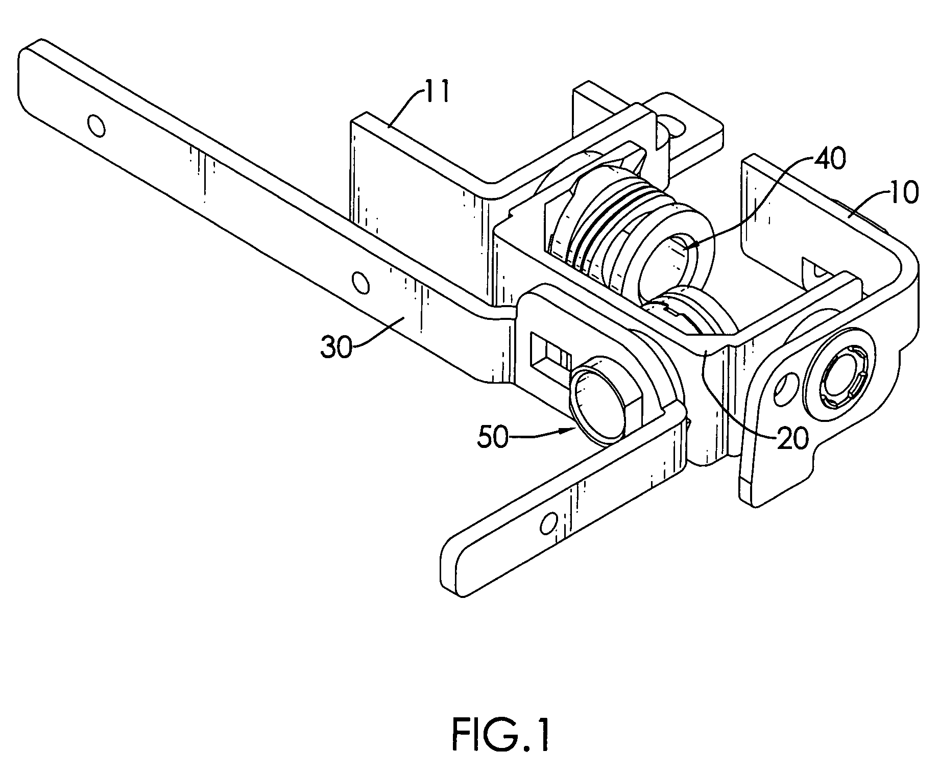
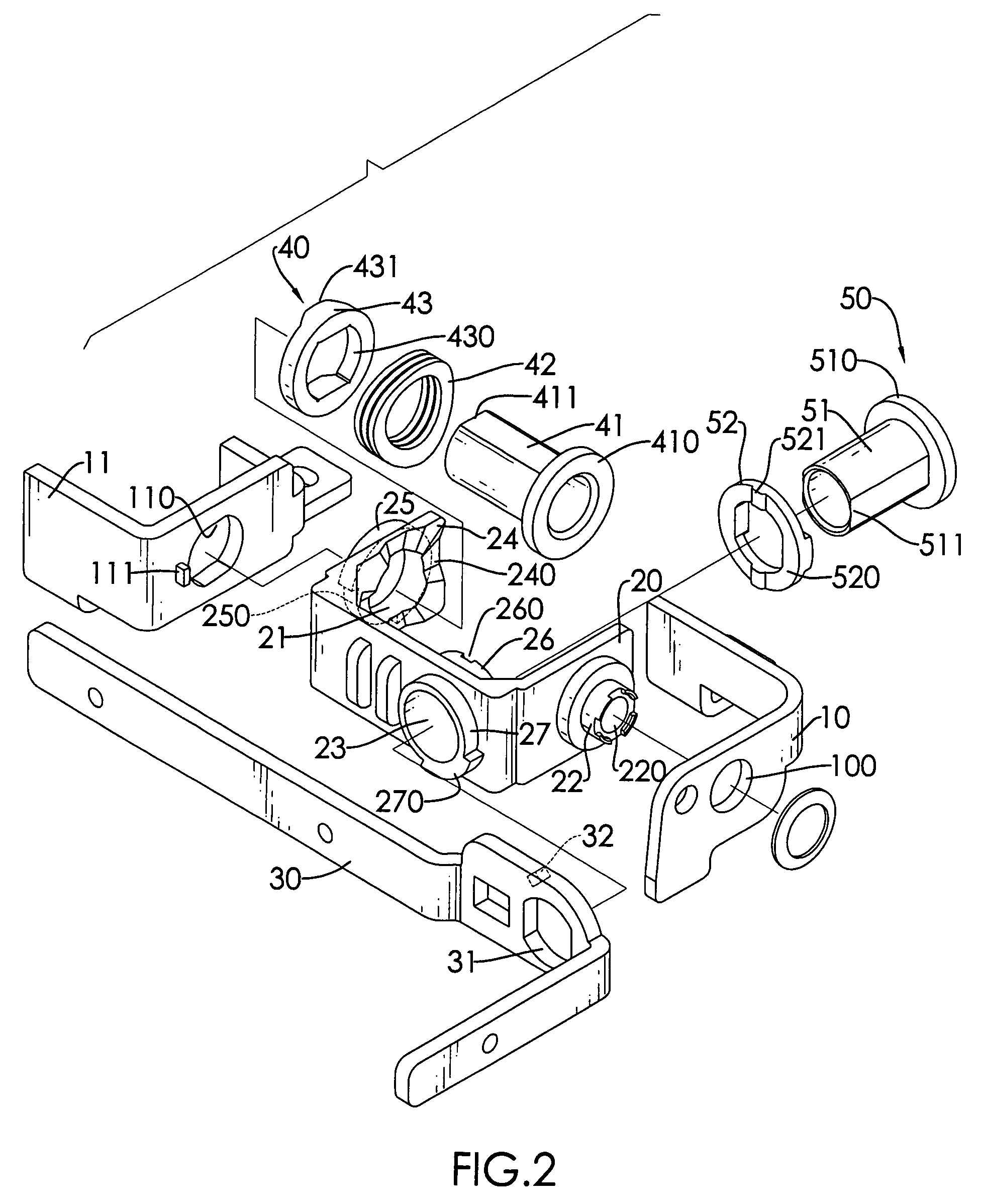
[0028]With reference to FIGS. 1, 2, and 3, in the first embodiment, the first stationary bracket (11) is “L” shaped and has at least one fixing hole, a surface, a non-circular first mounting hole (110) formed through the first stationary bracket (11) and a first stop (111) protruding from the surface adjacent to the first mounting hole (110). The second stationary bracket (10) is “L” shaped and separated from the first stationary bracket (11) and has at least one fixing hole, a surface and a second mounting hole (100) formed through the second stationary bracket (10) and coaxial with the first mounting hole (110).

[0029]The pivoting bracket (20) is pivotally mounted between the first stationary bracket (11) and the second stationary bracket (10), is “U” shaped and has a first end segment, a second end segment and a middle segment.

[0030]The first end segment is adjacent to the first stationary bracket (11) and has an inside surface, an outside surface, a first pivoting hole (21), an e...

second embodiment

[0036]With reference to FIGS. 7 and 8, in the second embodiment, the first stationary bracket (11′) is “L” shaped and has a surface, at least one fixing hole and a non-circular first mounting hole (110′) formed through the surface. The second stationary bracket (10′) is “L” shaped and separated from the first stationary bracket (11′) and has at least one fixing hole and a second mounting hole formed through the surface and is coaxial with the first mounting hole (110′).

[0037]The pivoting bracket (20′) is pivotally mounted between the first stationary bracket (11′) and the second stationary bracket (10′), is “U” shaped and has a first end segment, a second end segment and a middle segment.

[0038]The first end segment is adjacent to the first stationary bracket (11′) and has an inside surface, an outside surface, a first pivoting hole (21′), an engaging portion (210′) and a first stop (211′). The first pivoting hole (21′) is formed through the pivoting bracket (20′), corresponds to the...


PUM


Abstract

A dual-axis hinge for a portable electronic device has at least one stationary bracket, a pivoting bracket and a connecting leaf. The stationary bracket is adapted to be mounted securely in a base of the portable electronic device. The pivoting bracket is mounted pivotally in the stationary bracket and pivot relative to the stationary bracket in a first axis. The connecting leaf is adapted to be connected with a cover of the portable electronic device, is pivotally mounted in the pivoting bracket and pivots relative to the pivoting bracket in a second axis that is in different direction from the first axis. With such an arrangement, the cover connected with the connecting leaf may pivot relative to the base in the first axis and the second axis respectively and allows the portable electronic device to make more motivation and contents to various applicability requirements.

Description

BACKGROUND OF THE INVENTION[0001]1. Field of the Invention[0002]The present invention relates to a hinge, and more particularly to a dual-axis hinge for a portable electronic device that allows a cover of a portable electronic device to pivot relative to a base in two axes in different directions.[0003]2. Description of Related Art[0004]Portable electronic devices such as notebook computers, cellular phones and the like are commonly used in daily life. Generally, a portable electronic device comprises a base, a cover and a hinge. The cover usually has a display. The hinge pivotally connects the cover to the base, and allows the cover to pivot away from the base when the electronic device is in use.[0005]However, as more and more functions or programs in the portable electronic device have been developed, said conventional hinges that pivot the cover in a single axis gradually become inadequate to use.[0006]To overcome the shortcomings, the present invention provides a dual-axis hing...

Claims


Application Information

Patent Timeline
Patent Type & Authority Patents(United States)
IPC IPC(8): E05D7/00
CPCG06F1/1616H04M1/0212G06F1/1681E05D3/10E05Y2900/606Y10T16/5387Y10T16/5472
Inventor CHEN, CHIA-HSIANG
Owner SHIN ZU SHING
Why Eureka
Try Eureka