
Electric door lock system for refrigerated display cases

a technology for electric door locks and display cases, which is applied in the direction of mechanical equipment, anti-theft devices, transportation and packaging, etc., can solve the problems that beer, wine and other cold alcoholic beverages cannot be sold on certain days or at certain times, and achieve the effect of saving employees the time and trouble of unlocking and not frustrating customers

Active Publication Date: 2009-10-20
ANTHONY INC
View PDF33 Cites 31 Cited by
  • Summary
  • Abstract
  • Description
  • Claims
  • Application Information

AI Technical Summary

Benefits of technology

The invention is an electric door lock assembly and method that includes a solenoid and a locking arm. The solenoid is mounted to a bracket and can move between retracted and extended positions. When the solenoid is energized, the bolt moves from an unlocked position to a locked position. The assembly can be used to lock doors of refrigerated display cases and the like. The invention also includes a timing mechanism that can automatically lock the doors at predetermined times, ensuring compliance with local laws. The method includes at least one of energizing or de-energizing the solenoid. The technical effects of the invention include improved security, convenience, and compliance with local laws.

Problems solved by technology

For example, in some areas of the country, beer, wine and other cold alcoholic beverages cannot be sold on certain days or at certain times of the day without violating local laws.

Method used


Image

  • Electric door lock system for refrigerated display cases
  • Electric door lock system for refrigerated display cases
  • Electric door lock system for refrigerated display cases

Examples


Embodiment Construction

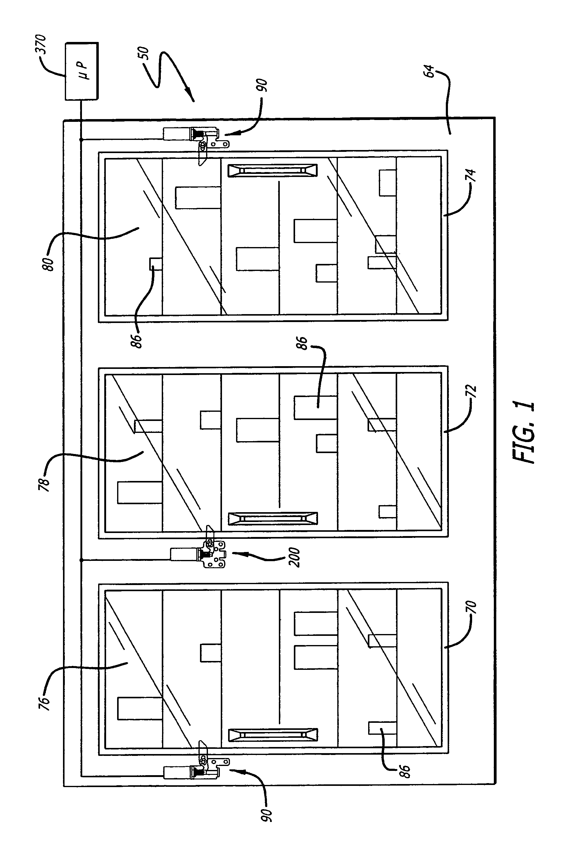
[0019]Referring to the drawings wherein like reference numerals in the various drawings indicate like parts, a refrigerated display case is shown in FIG. 1 generally at 50 positioned in a facility, such as a grocery or convenience store. The refrigerated display case 50 can include enclosure-forming walls, including a front wall 64. The case 50 has a suitable cooling system, such as cooling coils and fans (not shown and as would be known to those skilled in the refrigerated display case art), for keeping the contents at the desired cold temperature. Examples of display cases are disclosed in U.S. Pat. No. 5,675,983 (Ibrahim), U.S. Pat. No. 6,318,027 (Richardson, et al.), U.S. Pat. No. 6,367,223, (Richardson, et al.), U.S. Pat. No. 6,578,978 (Upton, et al.). (The entire contents of each of these patents and all other patents and other documents mentioned anywhere in this disclosure are hereby incorporated by reference.)

[0020]Wall 64 can have one or more customer-access openings, and ...


PUM


Abstract

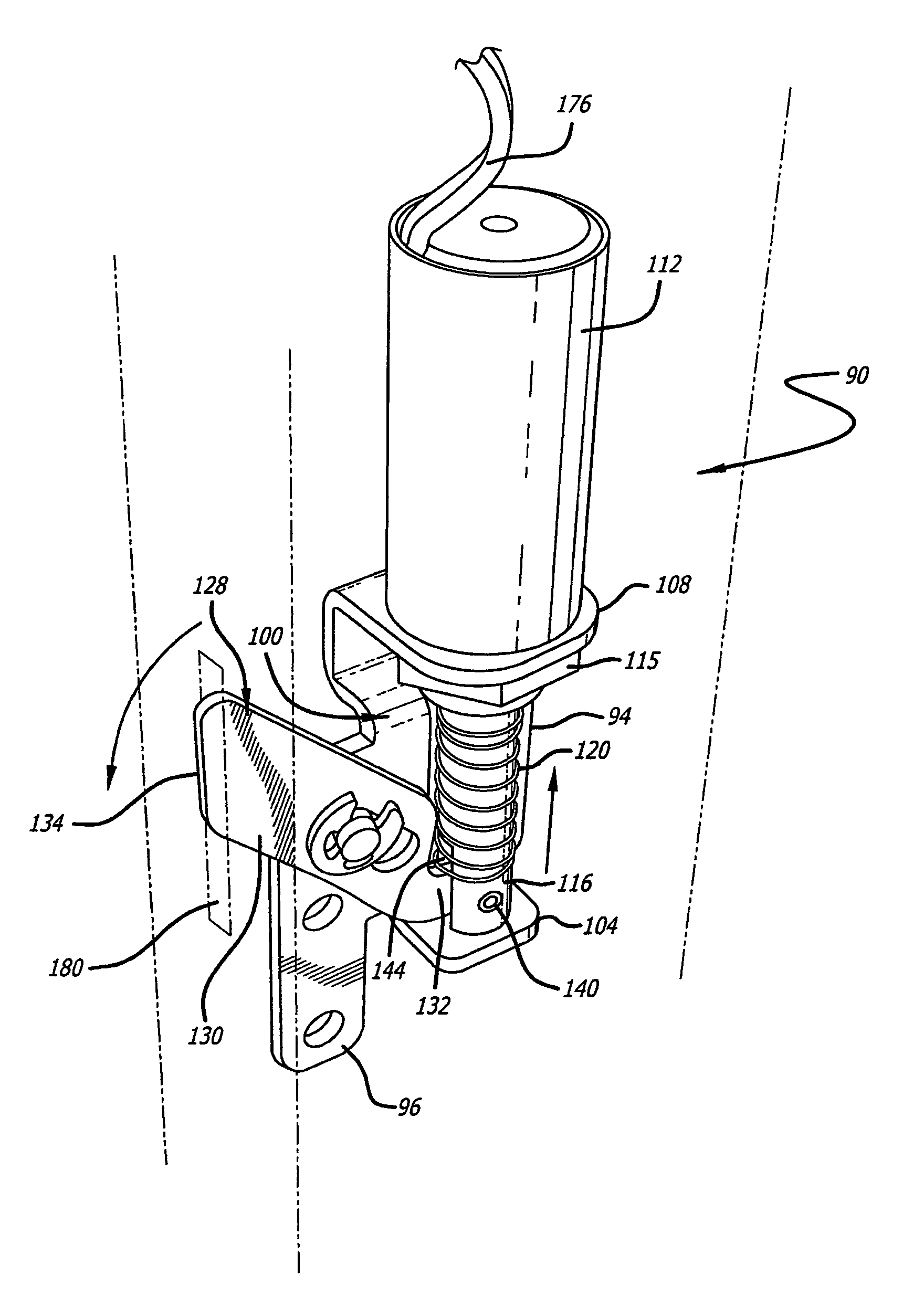
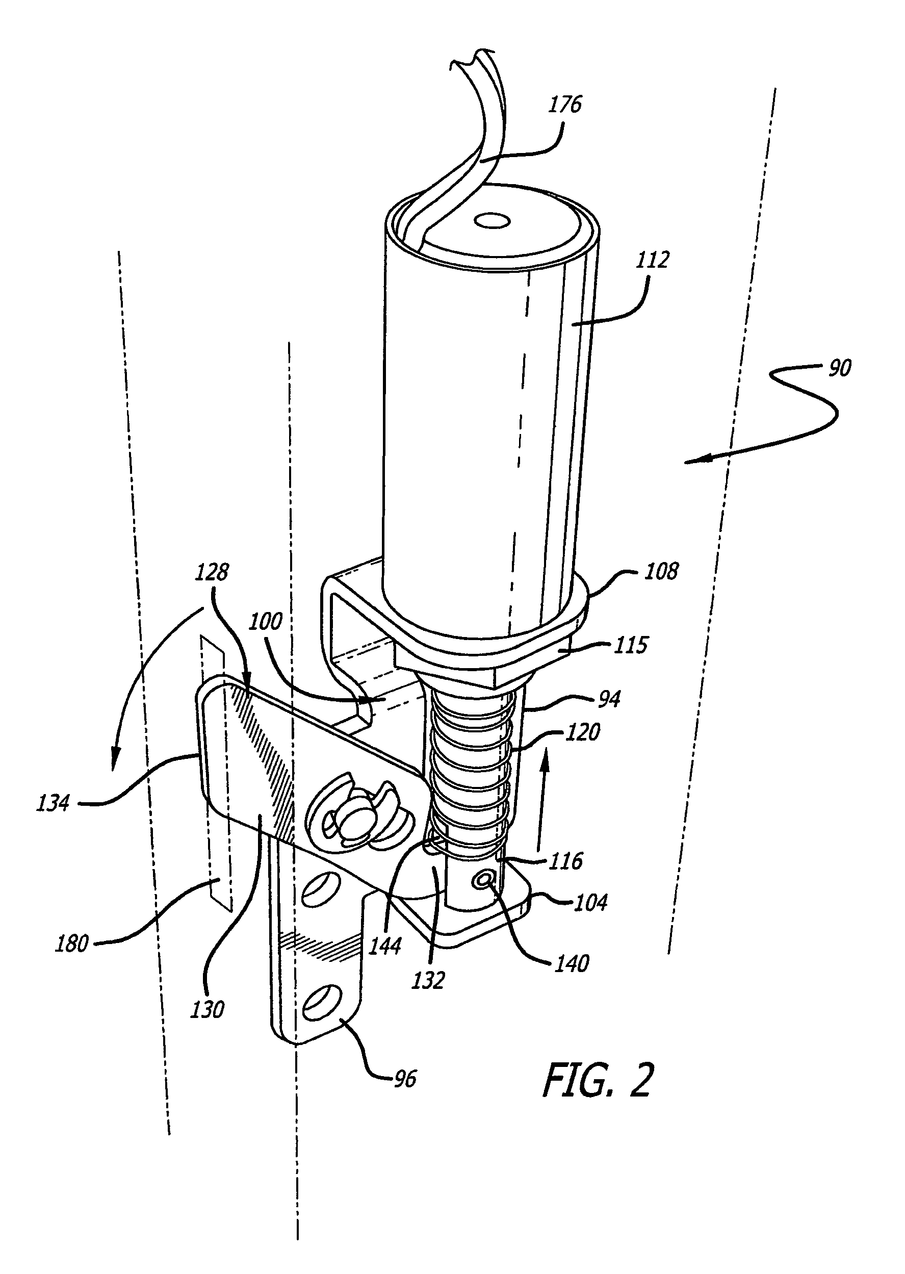
An electric door lock assembly including a solenoid having a plunger movable between retracted and extended positions, and a mounting bracket for mounting the solenoid to a door or door frame so that the plunger operatively moves along a vertical axis between the retracted and extended positions. A locking arm or bolt is pivotally connected at a proximal end thereof to the plunger. A connecting arrangement causes rotational and linear pivoting of the arm relative to a horizontal axis as the plunger is moved between the retracted and extended positions such that a distal end of the arm moves between unlocked and locked positions relative to a keeper in the door. This arrangement can include the locking arm having an elongate axial slot in which a fixed pin of the mounting bracket is positioned; the pivot pin defining the horizontal axis. The proximal end of the locking arm is pivotally connected to the bottom end of the plunger. Thereby, as the plunger travels up and down the proximal end moves up and down, and the locking arm slides relative to the pin, resulting in the rotational and linear pivoting.

Description

BACKGROUND OF THE INVENTION[0001]Refrigerated display cases are used in liquor stores, convenience stores, food vending establishments, and other facilities to keep food and beverage products cold, thereby to keep them fresh and / or to maintain them at desired cold consumable temperatures, or for some display cases to keep the products frozen. The products can be accessed by customers by sliding or pivoting the case doors open. The doors typically have transparent windows allowing customers to view the stored products before opening the doors to help the customers quickly determine whether the desired product is in the case before opening the door. This not only makes it easier for the customer but also reduces the frequency and length of time that the door is open and prevents ambient heat being transferred into the refrigerated display case.[0002]The refrigerated display case doors can have mechanical key-actuated locks to individually lock each of the doors when the facility is cl...

Claims


Application Information

Patent Timeline
Patent Type & Authority Patents(United States)
IPC IPC(8): E05B43/00
CPCA47F3/043E05B47/0002E05B47/023E05B47/0004E05C3/02E05B63/042E05B65/0042E05B2047/0077Y10T70/5978Y10T70/7006Y10T70/7062Y10T292/1082
Inventor CARBAJAL, FRANK J.ROLEK, MATTHEW
Owner ANTHONY INC
Learn More