
Wet gas metering using a differential pressure and a sonar based flow meter

a technology of differential pressure and flow meter, which is applied in the direction of volume/mass flow measurement, measurement devices, instruments, etc., can solve the problems of host of undesirable events and inability to accurately measure the amount of liquid carry-over

Active Publication Date: 2009-10-20
EXPRO METERS
View PDF96 Cites 25 Cited by
  • Summary
  • Abstract
  • Description
  • Claims
  • Application Information

AI Technical Summary

Benefits of technology

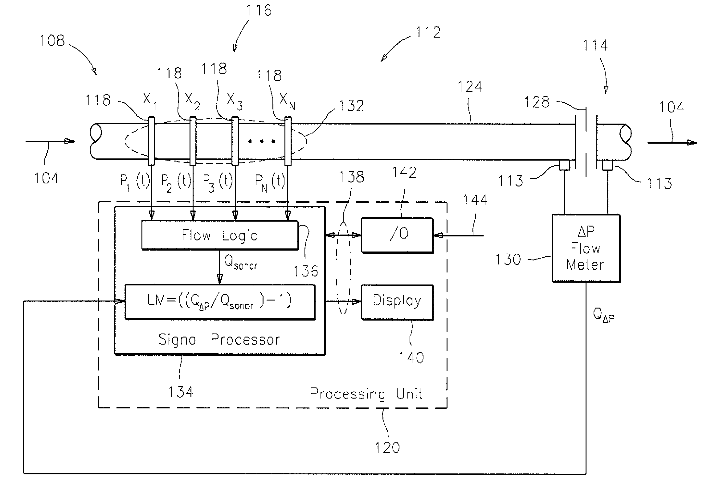
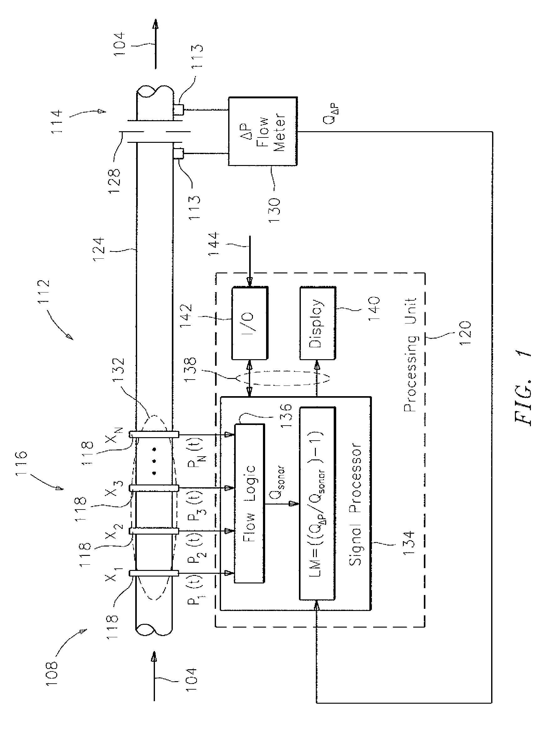
"The patent describes an apparatus and method for measuring the wetness of a wet gas flow or mixture. The apparatus includes a differential pressure based flow meter and a second flow meter with sensors to determine the volumetric flow rate of the wet gas flow. The processing device is then able to determine the wetness of the wet gas flow, the volumetric flow of the liquid portion of the wet gas flow, and the volumetric flow of the gas portion of the wet gas flow using the first and second volumetric flow rates. The apparatus can also include a first metering device for measuring a differential pressure that is sensitive to wetness and a second metering device for measuring a differential pressure that is relatively insensitive to wetness. The processing device is then able to determine the parameter of the wet gas flow using the first and second characteristics. Overall, the apparatus and method provide a reliable and accurate way to measure the wetness of a wet gas flow or mixture."

Problems solved by technology

This is undesirable because the liquid carry-over can result in a host of undesirable events depending in large part on the degree of carry-over that takes place.
Unfortunately however, accurate measurements of the amount of liquid carry-over have not been obtainable because devices and / or methods for accurately determining the amount of liquid carried over into the gas leg do not currently exist.

Method used


Image

  • Wet gas metering using a differential pressure and a sonar based flow meter
  • Wet gas metering using a differential pressure and a sonar based flow meter
  • Wet gas metering using a differential pressure and a sonar based flow meter

Examples


Embodiment Construction

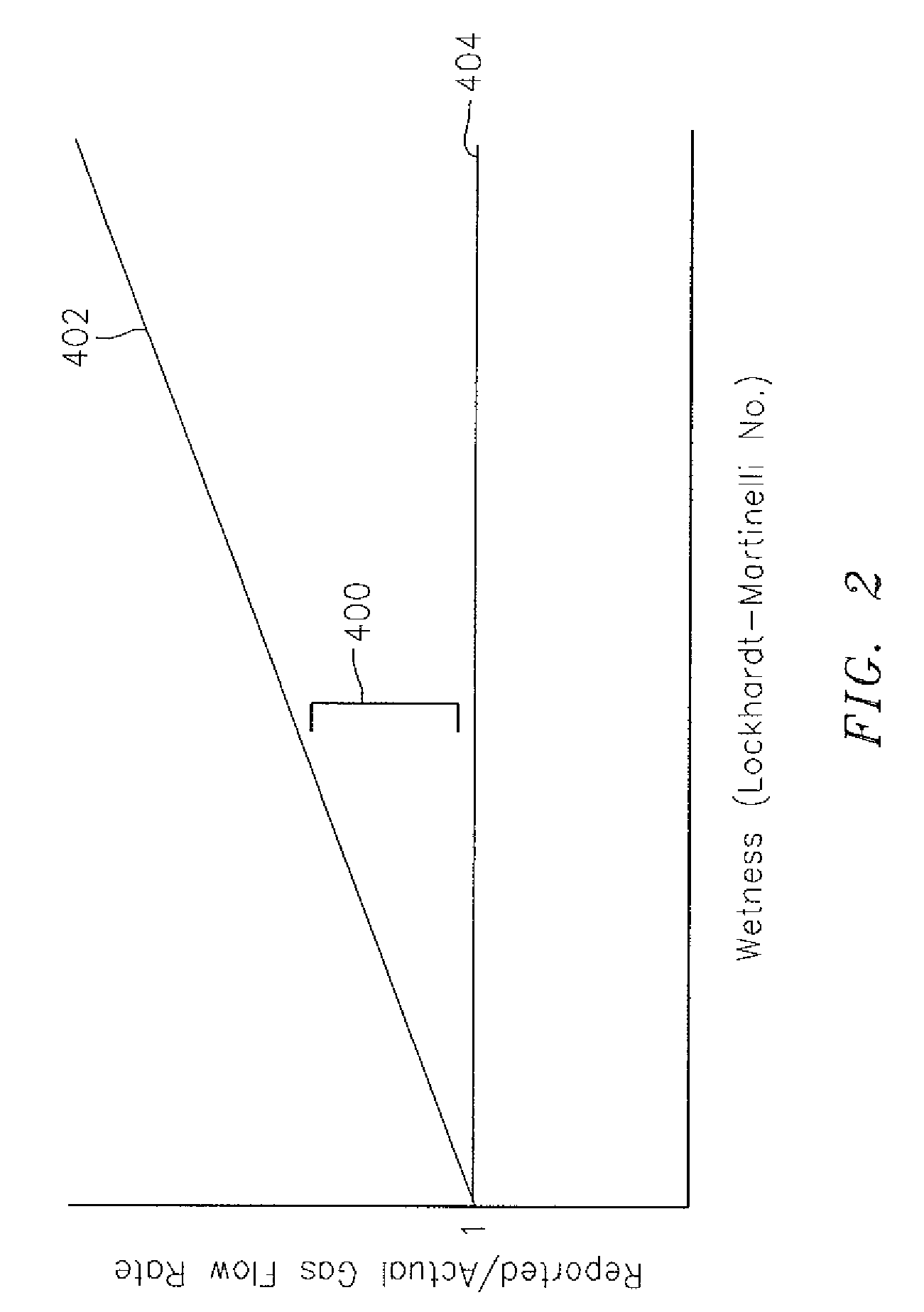
[0023]Differential pressure-based (DP) flowmeters, such as venturi type flowmeters, are widely used to monitor gas production and are well-known to over-report the gas flow rates in the presence of liquids, wherein this tendency to over report due to wetness indicates a strong correlation with the liquid to gas mass ratio of the flow. As used herein, the term “differential pressure-based flowmeter” or “DP flowmeter” refers to a device that is operable to determine a pressure drop of a flow of fluid, or gas, or mixture thereof, traveling within a pipe across a constriction within that pipe, or through a flow length of pipe. Examples of DP flowmeters that utilize a constriction include, but are not limited to, venturi, orifice, elbow, V-cone, and wedge type flow meters. Additionally, it has been observed that sonar type flowmeters (which do not utilize a constriction within a pipe), as will be described hereinafter, continue to accurately report gas flow rates, independent of the liqu...


PUM


Abstract

A method and apparatus for measuring wetness of a gas flow within a conduit is provided that includes a first pressure sensor, a second pressure sensor, a sonar based flowmeter, and a processing device. The first pressure sensor is operable to sense the pressure of the gas flow within the conduit at a first position. The second pressure sensor is operable to sense the pressure of the gas flow within the conduit at a second position. The second position is located downstream of the first position an amount sufficient that the gas flow experiences a pressure drop. The sonar based flowmeter is configured to determine a volumetric flow rate of the gas flow. The processing device is in communication with the first and second pressure sensors and the sonar based flowmeter. The processing device is adapted to determine a difference in the pressure sensed by the first and second pressure sensors, and to determine the wetness of the gas flow using the difference in pressure and the volumetric flow rate.

Description

CROSS-REFERENCE TO RELATED PATENT APPLICATIONS[0001]This application claims the benefit of U.S. Provisional Patent Application No. 60 / 881,069 filed Jan. 17, 2007, U.S. Provisional Patent Application No. 60 / 880,266 filed Jan. 11, 2007, and is a continuation-in-part of U.S. patent application Ser. No. 11 / 482,871 filed Jul. 7, 2006, now U.S. Pat. No. 7,418,877 which application claims priority to U.S. Provisional Patent Application No. 60 / 760,845 filed Jan. 19, 2006, U.S. Provisional Patent Application No. 60 / 759,159 filed Jan. 12, 2006; U.S. Provisional Patent Application No. 60 / 758,382 filed Jan. 11, 2006; U.S. Provisional Patent Application No. 60 / 724,952 filed Oct. 6, 2005; U.S. Provisional Patent Application No. 60 / 697,479 filed Jul. 7, 2005, U.S. Provisional Patent Application No. 60 / 762,101 filed Jan. 24, 2006; U.S. Provisional Patent Application No. 60 / 773,146 filed Feb. 13, 2006, U.S. Provisional Patent Application No. 60 / 774,706 filed Feb. 17, 2006; and U.S. Provisional Paten...

Claims


Application Information

Patent Timeline
Patent Type & Authority Patents(United States)
IPC IPC(8): G01F1/34G01F1/7082
CPCG01F1/36G01F1/666G01F15/08G01F1/712G01F1/74G01F1/7082
Inventor GYSLING, DANIEL L.
Owner EXPRO METERS
Learn More