Loading device for the at least partially automated loading and unloading of a cargo hold on transport equipment as well as a conveying system

a technology of loading device and cargo hold, which is applied in the direction of loading/unloading, aircraft accessories, vehicles with endless chains/belts, etc., can solve the problem and achieve the effect of reducing the probability of failure of the entire loading devi

Inactive Publication Date: 2009-10-20
AIRBUS OPERATIONS GMBH
View PDF26 Cites 22 Cited by
  • Summary
  • Abstract
  • Description
  • Claims
  • Application Information

AI Technical Summary

Benefits of technology

[0016]Because each conveying system may have at least one sensor, wherein the sensor or sensors may detect the presence of a cargo unit in the area of the conveying system without contact, and at least the position of a cargo unit on the floor space may be determined in at least two spatial dimensions without contact, operation of the conveying systems in the cargo hold of a transport equipment, in particular an aircraft may be wear-free and low-maintenance. In addition, each conveying system may need only exhibit one sensor, which simultaneously may assume the task of the “scrab” sensor and the previous optical sensors. In addition, the positions of the cargo units on the floor space of the cargo hold may be determined using the new type of sensors via the conveying system in at least two spatial dimensions, e.g., simultaneously in the x-direction and y-direction of the space. Therefore, the cargo units may be positioned on the floor space of the cargo hold as desired by the loading device according to the invention by suitably actuating the conveying systems with a an open and / or closed loop controller. The fact that there is only one sensor also reduces the probability of failure of the entire loading device.
[0018]In addition to possibly acquiring the absolute position of the cargo unit in at least two spatial dimensions, this configuration may make it possible to determine the velocity of the cargo unit in at least two directions in space as additional information for more precisely controlling the sequence of movements of the cargo units on the floor space of the cargo hold.
[0020]This configuration may make it possible to determine the acceleration of a cargo unit in at least two directions in space as additional control information.
[0022]This may enable a largely wear-free, and hence low-maintenance, operation of the conveying systems inside the loading device.
[0027]Because each conveying system may have at least one sensor, wherein the sensor or sensors may be used to detect the presence of a cargo unit in the area of the conveying system without contact, and at least the position of a cargo unit may be acquired on the floor space in at least two spatial dimensions without contact, the conveying system according to an embodiment of the invention integrated in the loading device for the at least partially automated loading and unloading of a cargo hold of transport equipment may be operated largely without wear and maintenance free. In addition, acquiring the position of a cargo unit on the floor space of the cargo hold in at least two spatial dimensions may make it possible to control complex sequences of movements by the cargo units on the floor space of the cargo hold. Further, the statistical probability of failure for the entire loading device may be decreased by the presence of only one sensor per conveying system.

Problems solved by technology

The fact that there is only one sensor also reduces the probability of failure of the entire loading device.

Method used


Image

  • Loading device for the at least partially automated loading and unloading of a cargo hold on transport equipment as well as a conveying system
  • Loading device for the at least partially automated loading and unloading of a cargo hold on transport equipment as well as a conveying system
  • Loading device for the at least partially automated loading and unloading of a cargo hold on transport equipment as well as a conveying system

Examples


Embodiment Construction

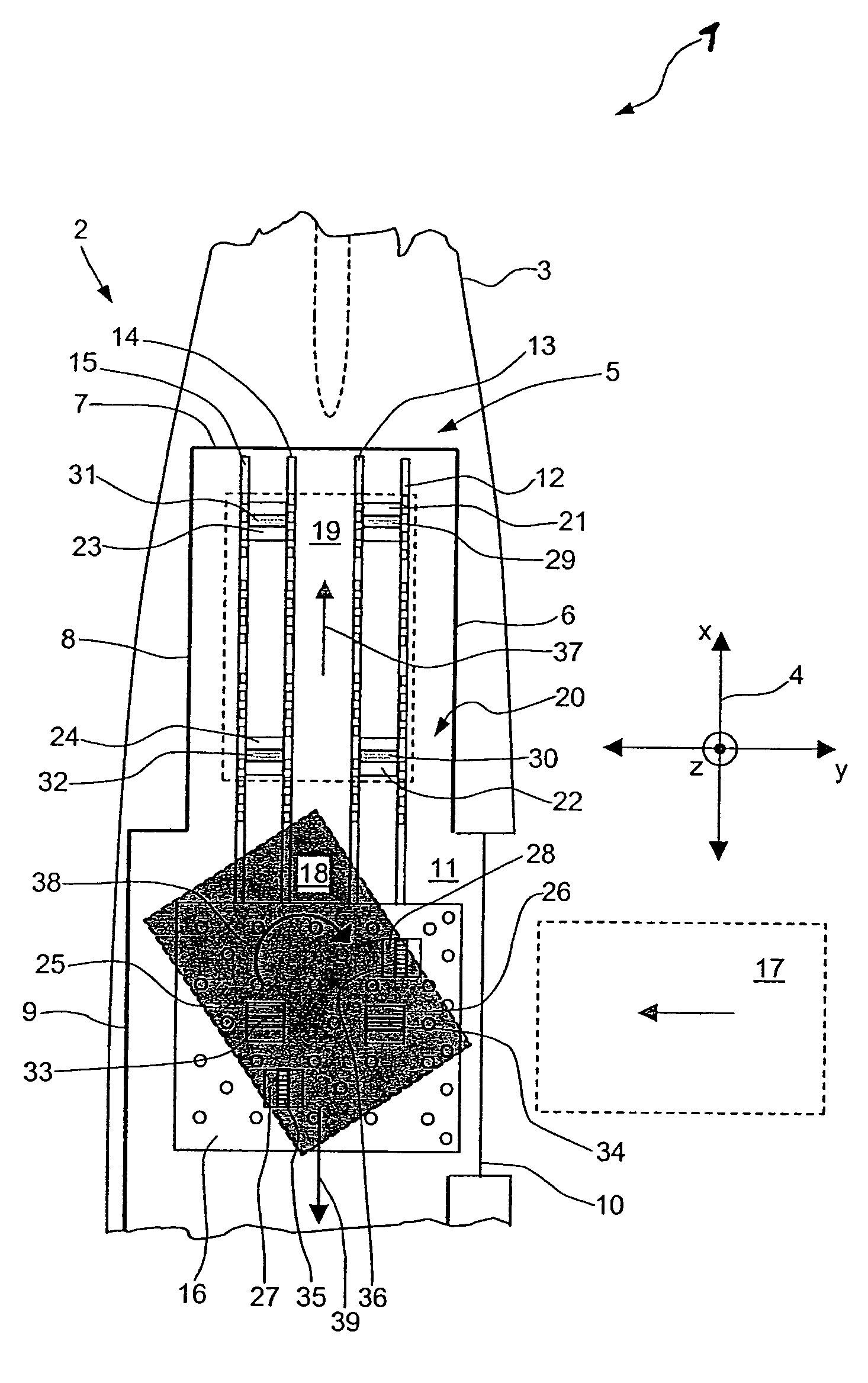
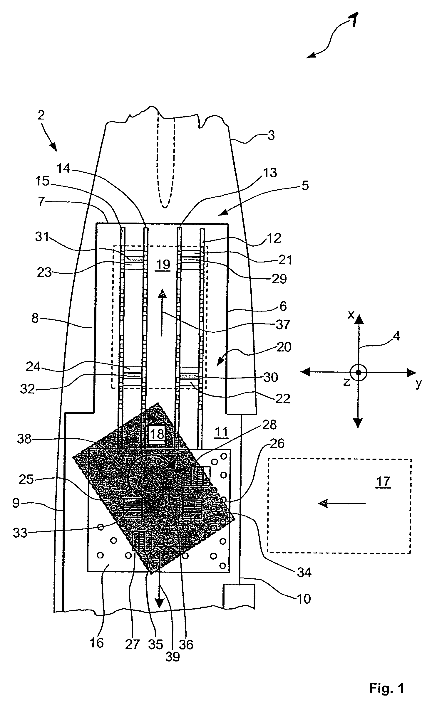
[0031]FIG. 1 shows a diagrammatic top view of the loading device according to an exemplary embodiment of the invention within a cargo hold arranged inside the tail section of an aircraft.

[0032]The loading device 1 according to the exemplary embodiment of the invention is integrated in the tail section 2 of an aircraft 3 in the exemplary embodiment shown. A rectangular coordinate system 4 is shown on FIG. 1 with an x, y and z-axis in order to illustrate the three directions in space. Cargo hold walls 6 to 9 envelop a cargo hold 5. A loading gate 10 is used to close the cargo hold 5 after loading and / or for unloading. A rear area of the floor space 11 of the cargo hold 5 accommodates the roller paths 12 to 15 as a movement aid. A ball mat 16 is situated in the area of the loading gate 10 as a movement aid. The ball mat 16 encompasses a plurality of balls arranged in a matrix as denoted on FIG. 1 by small circles, the surfaces of which project out of boreholes in the ball mat 16, at le...


PUM


Abstract

A loading device 1 for loading and unloading of a cargo hold having at least one conveying system for positioning cargo units in the area of a floor space of the cargo hold, and with at least one guiding element guiding the conveying, and a movement aid in the area of the floor space 11 of the cargo hold 5 enabling rotation and movement of the cargo unit. Sensors detect the presence of a cargo unit in the area of the conveying system without contact the position of a cargo unit on the floor space is determined in at least two spatial dimensions without contact. The sensors make it possible to control rotating movements of the cargo units in the area of the respective conveying systems by a controller.

Description

[0001]This application claims the benefit of German Patent Application No. 10 2005 008 443.5 filed Feb. 24, 2005, the disclosure of which is hereby incorporated herein by reference.FIELD OF THE INVENTION[0002]The invention relates to a loading device for the at least partially automated loading and unloading of a cargo hold on transport equipment, in particular a cargo hold on an aircraft, with at least one conveying system for positioning cargo units in the area of a floor space of the cargo hold, and with at least one guiding element, as well as at least one movement aid in the area of the floor space of the cargo hold.[0003]In addition, the invention relates to a conveying system, in particular for a loading device for the at least partially automated loading and unloading of a cargo hold of a transport equipment, in particular a cargo hold on an aircraft, with at least one conveying unit, in particular with at least one driven transport roller.TECHNOLOGICAL BACKGROUND[0004]Known...

Claims


Application Information

Patent Timeline
Patent Type & Authority Patents(United States)
IPC IPC(8): B64C1/22
CPCB64D9/00B60P1/36
Inventor JACOBSEN, RUEDIGERVOGEL, THOMAS
Owner AIRBUS OPERATIONS GMBH
Why Eureka
Try Eureka