Electrical adaptor

a technology of electrical adaptor and extension cord, which is applied in the direction of coupling device connection, coupling protective earth/shielding arrangement, electric discharge lamps, etc., can solve the problems of extension cord being a fire hazard, trip hazard, and inaccessible to use,

Inactive Publication Date: 2009-10-20
JOHNSON STEVE O
View PDF20 Cites 25 Cited by
  • Summary
  • Abstract
  • Description
  • Claims
  • Application Information

AI Technical Summary

Benefits of technology

[0012]The present invention is an electrical adaptor which provides a solution to the shortcomings of the prior art by providing a small rigid single piece electrical adaptor which can be plugged into a receptacle to redirect the interface of the receptacle such that when a plug is connected to it the cord from the plug will hang at an angle parallel with the wall.

Problems solved by technology

The occupant is often faced with the dilemma of either placing the furniture several inches out from the wall so that the receptacle can be accessed for use or placing the furniture flush against the wall, thus leaving the receptacle inaccessible for use.
This problem is compounded when the occupant has an appliance which has a grounded plug and the receptacle is ungrounded.
However, extension cords can be a fire hazard and a trip hazard in certain applications.
They also present unsightly clutter.
Other adaptors have been presented to solve this problem however they typically are rather complicated devices with moving parts which increase the likelihood of failure of the adaptor.
Addressing the issue of plugging the grounded plug into the ungrounded receptacle, the occupant has had one of three unsatisfactory options to solve this problem.
The first option would be to cut off the grounding prong on the plug, however this leaves the appliance ungrounded and thus presents a danger of electrocuting the occupant.
While this does allow for grounding of the appliance, the extra step of having to unscrew and then reattach grounding screw with the grounding wire is inconvenient as many times the occupant does not have a screw driver handy.
Also as the adaptor ages the coating on the grounding wire can become brittle and break and the wire can become frayed thus creating a danger of electrocution and / or fire.
In addition to having the same drawbacks as the adaptor with the grounding wire the adaptor with a grounding tab can only provide grounding when used in the top receptacle.
The other draw back of using either one of these adaptors is that they cause the plug to stick out further from the wall, typically 1″ to 1½″ thus further complicating the location of furniture in front of the receptacle.

Method used


Image

  • Electrical adaptor
  • Electrical adaptor
  • Electrical adaptor

Examples


first embodiment

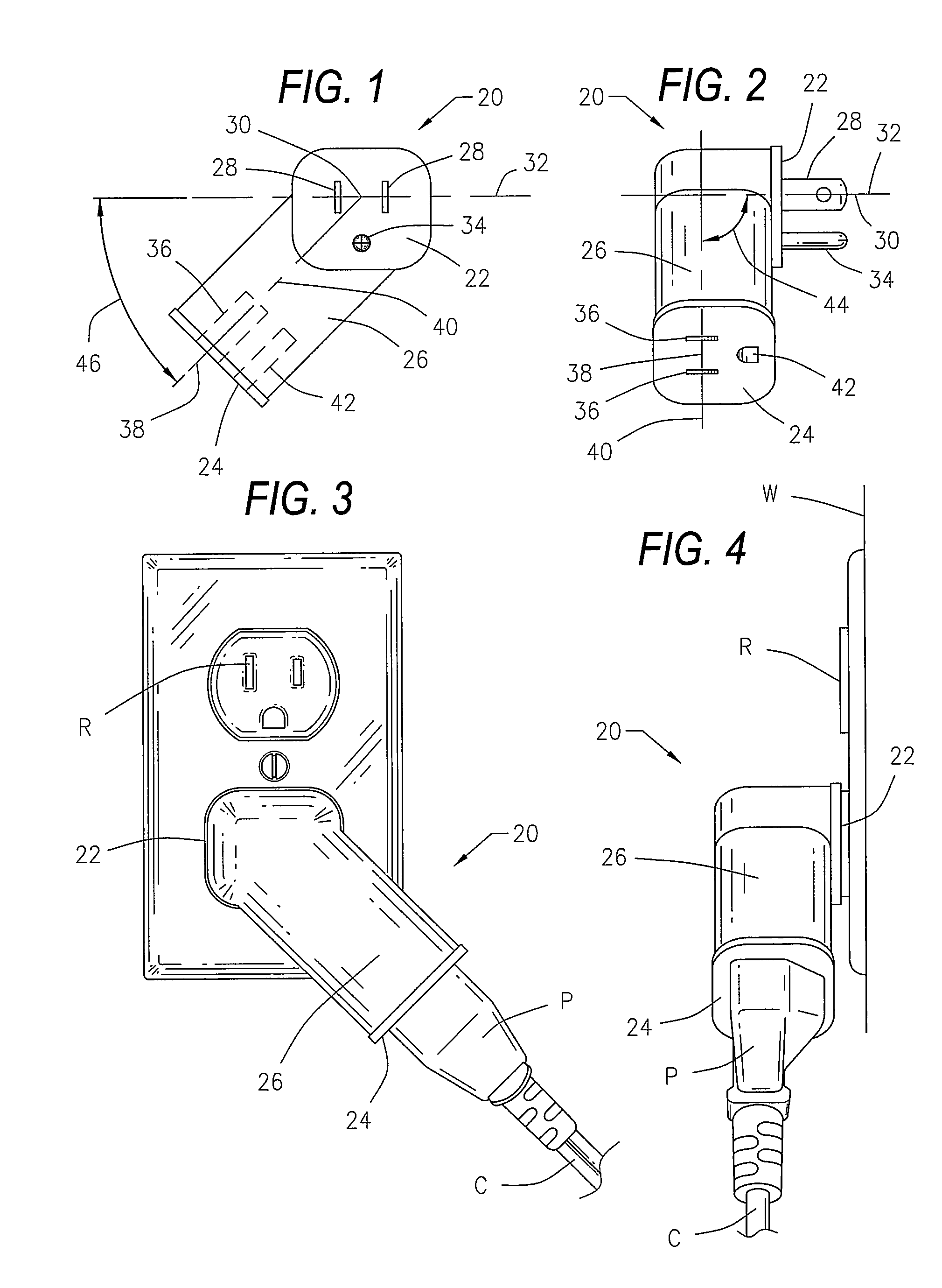
[0028]In the first embodiment the body is configured such that the center line 30 of the pair of male connectors 28 is perpendicular to the center line 38 of the pair of female connectors 36. This angle is indicated by element 44 in FIG. 2. The center line 38 of the pair of female connectors 36 is also at an angle 46 relative to the plane 32 of the pair of male connectors 28. This angle 46 can range from 30-60° with the preferred embodiment being 45°.

[0029]FIGS. 3 and 4 show the adaptor 20 of the present invention in use with a typical 120V receptacle R and an electrical plug P. When in use the pair of male connectors 28 and third male connector 34 are inserted into the female receptacle R. An electrical plug P can then be attached to the pair of female connectors 36 and third female connector 42. This allows the plug P and its cord C to lie flush with the wall W. This in turn allows for any furniture standing in front of the receptacle R to be pushed close to the wall W while still...

second embodiment

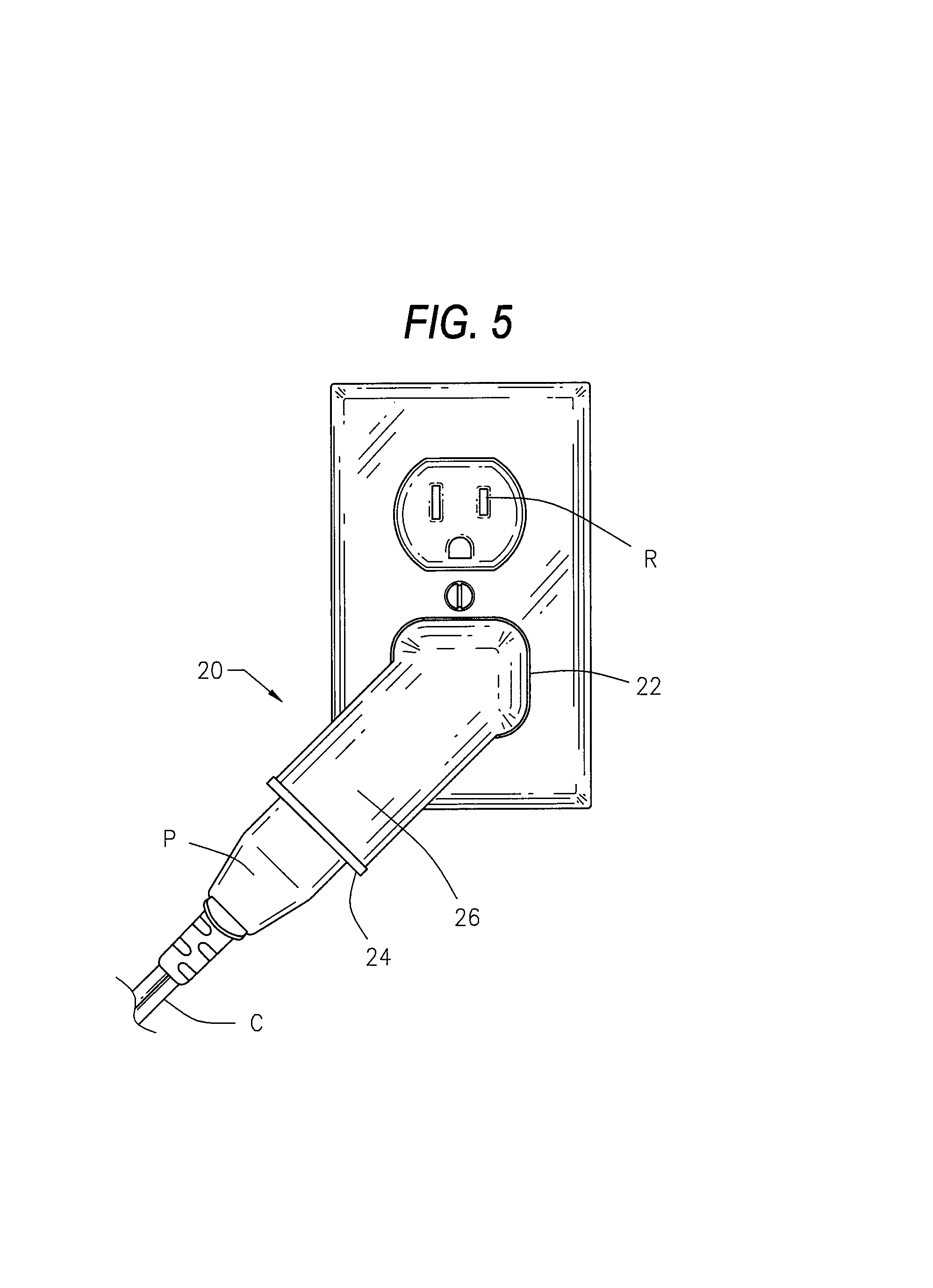
[0030]FIG. 5 shows the adaptor 20 of the present invention in use with a typical 120V receptacle R and an electrical plug P. FIG. 5 is included to illustrate the adaptor of the present invention can angle to the left (as shown in FIG. 5) in addition to angling to the right (as shown in FIG. 3). Other than the difference in the direction of angle, the embodiment shown in FIG. 5 is structurally the same as the embodiment shown in FIGS. 1 through 4. The two embodiments also operate in the same manner.

[0031]While the example shown in the figures is a three prong outlet with a ground or third connector 34 and 42, the invention can also be implemented using just the male and female pair of connectors 28 and 36. Likewise the invention can also be used on circuits with electrical voltages other than 120V.

third embodiment

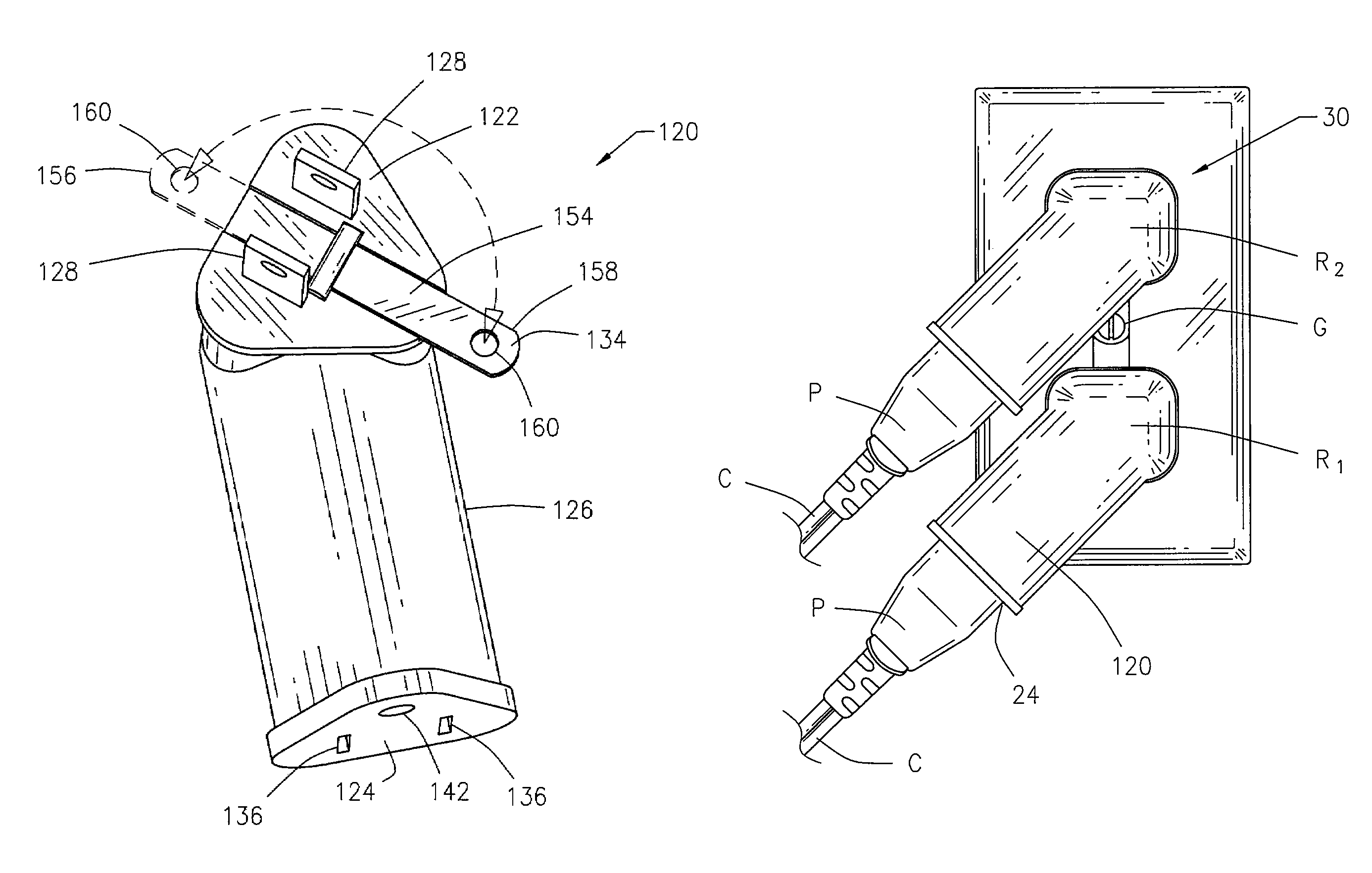
[0032]Turning now to FIG. 6, the electrical adaptor 120 of the present invention has a male face 122 and a female face 124 on either end of the body 126. A pair of male connectors 128 extend from the male face 122 as does a hinged third male connector 134. A pair of female connectors 136 and a third female connector 142 extend into the body 126 of the adaptor 120 from the female face 124. Each of the male connectors 128 are in electric conductive communication with one of the female connectors 136. The third male connector 134 is in electric conductive communication with the third female connector 142.

[0033]When the adaptor 120 is used with a 120V AC system one of the connectors of the pair of male connectors 128 will be the hot or electrified wire. The second male electrical connector in the pair 128 is the neutral side of the circuit. The third male connector 134 is the ground. Likewise one of the female connectors of the pair of female connectors 136 is the hot or electrified wir...


PUM


Abstract

An electrical adaptor providing access to an electrical receptacle with an object placed in close proximity directly in front of the receptacle. The electrical adaptor having a pair of male connectors with a center line; a pair of female connectors having a center line; the female connectors in electric conductive communication with the male connectors; a rigid single section body having a bend such that the center line of the female conductors is oriented and fixed at an angle of 90° relative to the center line of the male connectors and the center line of the female connectors is oriented and fixed at an angle of 30° to 60° from a plane formed by the male connectors; and the body extending from the male connectors to the female connectors.

Description

REFERENCE TO PENDING APPLICATIONS[0001]This application is a continuation-in-part patent application claiming priority to U.S. patent application Ser. No. 11 / 474,657, filed on Jun. 26, 2006.REFERENCE TO MICROFICHE APPENDIX[0002]This application is not referenced in any microfiche appendix.FIELD OF THE INVENTION[0003]The present invention is generally directed towards an improved electrical adaptor. More specifically, the present invention provides an adaptor which can be used to provide access to an electrical receptacle located behind a piece of furniture while allowing the furniture to sit tightly against the wall. Further the present invention provides the ability to use an appliance with a grounded plug in both sockets of an ungrounded receptacle while providing the ability to ground two of the adaptors the present invention to the grounding screw on the outlet.BACKGROUND OF THE INVENTION[0004]Electricity is a modern day necessity. Any building or home built today in the United ...

Claims


Application Information

Patent Timeline
Patent Type & Authority Patents(United States)
IPC IPC(8): H01R25/00
CPCH01R13/652H01R31/06H01R24/30H01R2103/00
Inventor JOHNSON, STEVE O.
Owner JOHNSON STEVE O
Why Eureka
Try Eureka