
Method for compensating for the positional errors of a sensor

a sensor and positional error technology, applied in the direction of direction finders, instruments, measurement devices, etc., can solve the problems of sensor position bias registration error, corrupted absolute positional reference estimates,

Active Publication Date: 2009-10-20
LOCKHEED MARTIN CORP
View PDF10 Cites 23 Cited by
  • Summary
  • Abstract
  • Description
  • Claims
  • Application Information

AI Technical Summary

Benefits of technology

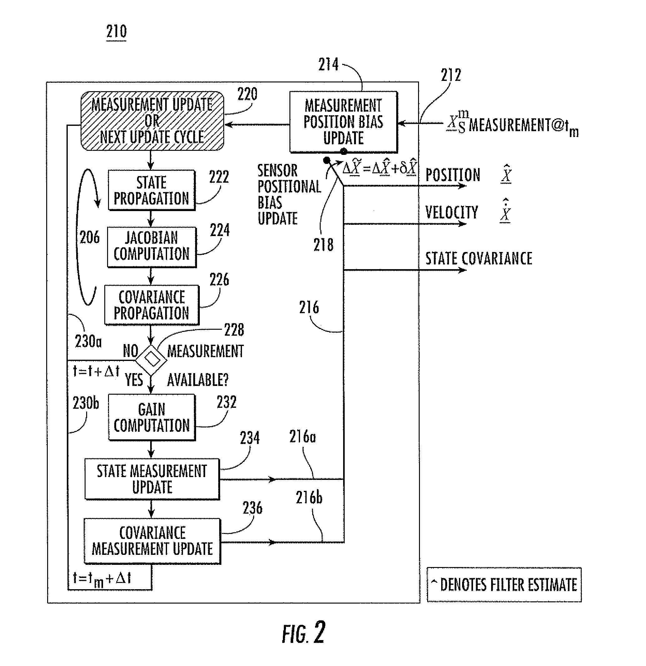
The invention relates to a method for compensating for positional errors of a sensor tracking a target with known acceleration. The method involves adding sensor positional bias update information to the sensed information to produce updated sensed information. The state of the target is then propagated to produce time updated state estimates of the target position and velocity. The method also includes computing the Jacobian of the state dynamics of the target and the state transition matrix for the extended Kalman filter algorithm. The covariance of a state vector comprising the position and velocity states of the target is also time propagated. The technical effect of the invention is to improve the accuracy of sensor positioning and target state estimation.

Problems solved by technology

However, such sensor position bias registration error can exist.
GPS receivers are, however, susceptible to jamming and spoofing failure modes, which can ultimately corrupt the absolute positional reference estimate.

Method used


Image

  • Method for compensating for the positional errors of a sensor
  • Method for compensating for the positional errors of a sensor
  • Method for compensating for the positional errors of a sensor

Examples


Embodiment Construction

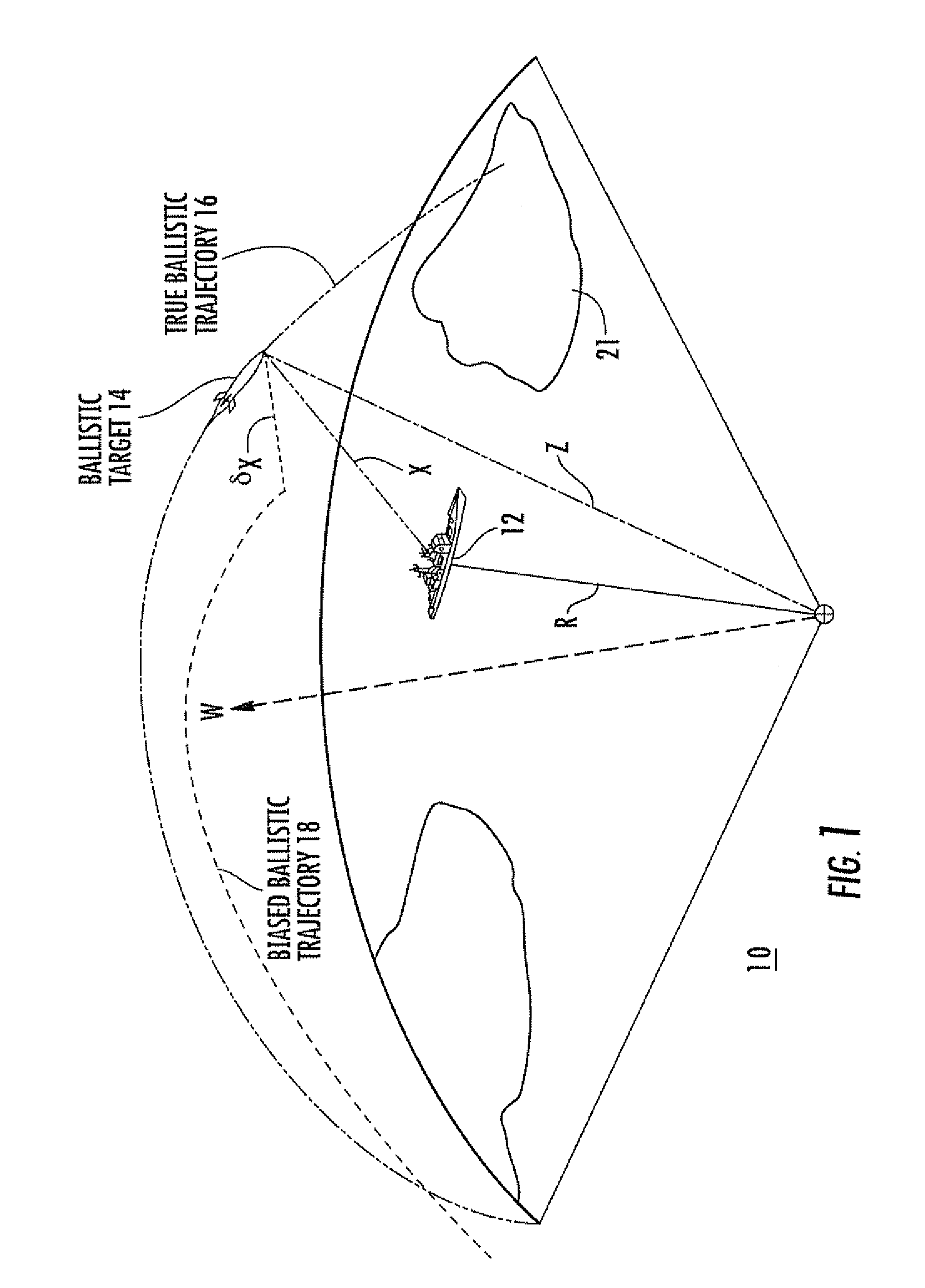
[0021]In general, the invention relates to a system called “Geo-Positional Sensor Level EStimation System” (GPSLESS). GPSLESS is a ballistic target track state estimator that incorporates an extended Kalman filter algorithm with an embedded real-time sensor registration estimator that estimates the positional sensor registration bias error. The intent is not to replace the GPS systems, but rather, GPSLESS provides a positional reference alternative, which may be used during GPS down times due to unavailability, jamming, or spoofing; or which may be used as a supplement to GPS. In some aspects of the invention, GPSLESS provides real-time updates to the positional bias registration error, while at the same time providing an enhanced ballistic track state estimate, unencumbered by positional registration bias errors. In other aspects, GPSLESS achieves positional sensor registration relative to the local geodetic coordinate frame for systems where the target acceleration is known, e.g. ...


PUM


Abstract

A method for determining or compensating for the positional errors of a sensor tracking a target comprises the steps of operating the sensor to generate sensed information relating to the target and adding any sensor positional bias update information to produce updated sensed information. The target state is propagated to produce time updated state estimates. The Jacobian of the state dynamics and the state transition matrix for the extended Kalman filter algorithm are computed. The covariance of a state vector is time propagated using the state transition matrix.

Description

FIELD OF THE INVENTION[0001]This invention relates to methods for determining the position and velocity states of a target when the position bias of the observing sensor is not accurately known, or for determining the location of the sensor when there is an uncertainty in the sensor location.BACKGROUND OF THE INVENTION[0002]Collaborative sensor coordination among the systems of a system of systems (SOS) is currently being pursued by the Missile Defense Agency (MDA) to enhance both targeting and cueing accuracies in support of ballistic missile defense. Collaborative sensor coordination requires each element of Ballistic Missile Defense System (BMDS) to register its sensor(s) to local geodetic coordinate systems in order to minimize tracking and guidance errors, thereby reducing system handover and guidance errors between the target tracking and / or cueing systems and the interceptor(s). Ultimately this “sensor registration” provides additional margin to the weapon system's pointing a...

Claims


Application Information

Patent Timeline
Patent Type & Authority Patents(United States)
IPC IPC(8): G01S13/72
CPCG01S13/723G01S7/4004
Inventor MOOKERJEE, PURUSOTTAMBOKA, JEFFREY B.
Owner LOCKHEED MARTIN CORP
Learn More