Landmark detection apparatus and method for intelligent system

a detection apparatus and intelligent system technology, applied in the direction of instruments, navigation instruments, process and machine control, etc., can solve the problems of difficult to extract optimal landmarks in actual environments, low landmark localization success rate, and high time consumption, so as to improve detection accuracy and strong resistance to noise

Inactive Publication Date: 2009-10-20
SAMSUNG ELECTRONICS CO LTD
View PDF3 Cites 37 Cited by
  • Summary
  • Abstract
  • Description
  • Claims
  • Application Information

AI Technical Summary

Benefits of technology

[0010]The invention provides a landmark detection apparatus and method having strong resistance to noise and improved detection accuracy by setting an entire region of a frame image as a sampling region, setting a degree of dispersion to a high value, performing first landmark detection, estimating a position of a landmark, setting a region around the estimated position of the landmark as a sampling region, setting the degree of dispersion to a low value, and performing second landmark detection.
[0011]The invention also provides a landmark detection apparatus and method capable of improving accuracy of landmark detection by adaptively adjusting a degree of dispersion applied to each frame in first and second landmark detections using a highest matching probability obtained from a current frame image.
[0012]The invention also provides a landmark detection apparatus and method with stronger resistance to luminance changes by updating a color histogram of a landmark model using a matching probability obtained from a current frame image, color histograms of sample blocks used in the current frame image, and a color histogram of the landmark model used in the current frame image.

Problems solved by technology

However, localization using a natural landmark has a disadvantage in that it is difficult to extract an optimal landmark in an actual environment.
Since a localization method using information regarding certain forms of a landmark is heavily dependent on results of image processing, a landmark localization success rate is low due to a blurring phenomenon caused by noise or inaccurate focus in an image.
Therefore, in the CONDENSATION algorithm, landmark detection requires a lot of time, and, if the initial value of the degree of dispersion is set to a high value, detection accuracy is undermined.

Method used


Image

  • Landmark detection apparatus and method for intelligent system
  • Landmark detection apparatus and method for intelligent system
  • Landmark detection apparatus and method for intelligent system

Examples


Embodiment Construction

[0026]The invention will now be described more fully with reference to the accompanying drawings, in which exemplary embodiments of the invention are shown. The invention may, however, be embodied in many different forms and should not be construed as being limited to the embodiments set forth therein; rather, these embodiments are provided so that this disclosure will be thorough and complete, and will fully convey the concept of the invention to those skilled in the art.

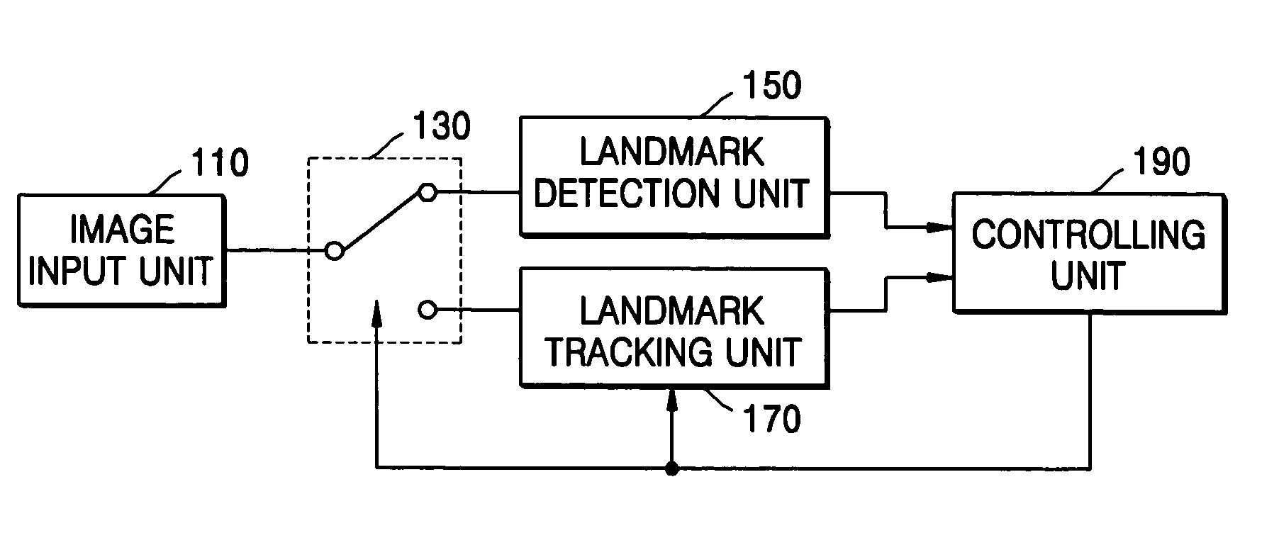
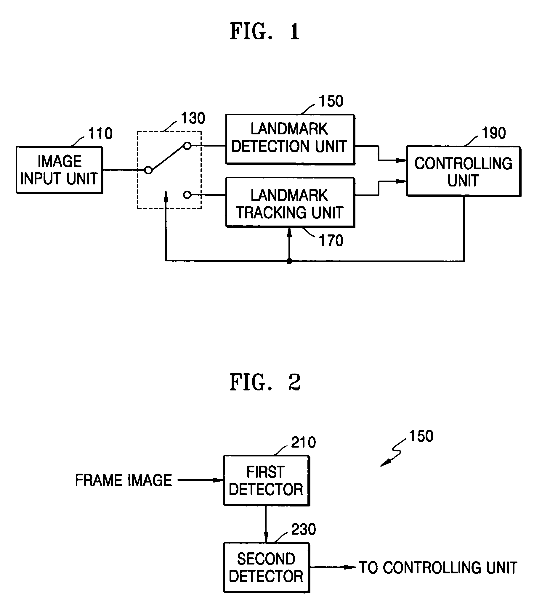
[0027]FIG. 1 is a block diagram of a landmark detection apparatus of an intelligent system according to an exemplary embodiment of the invention. The landmark detection apparatus includes an image input unit 110, a switching unit 130, a landmark detection unit 150, a landmark tracking unit 170, and a controlling unit 190. The landmark detection unit 150 includes a first detector 210 and a second detector 230 as illustrated in FIG. 2. Here, the switching unit 130, the landmark tracking unit 170, and the controlling ...


PUM


Abstract

A landmark detection apparatus and method, the apparatus including a first detection unit that generates N first sample blocks in a first sampling region using a first weighted sampling method according to a first degree of dispersion, and that performs a first landmark detection by comparing a feature of each first sample block a feature of a landmark model, where the first sample region is set to the entirety of a current frame image; and a second detection unit that generates N second sample blocks in a second sampling region using a second weighted sampling method according to a second degree of dispersion, and that performs a second landmark detection by comparing a feature of each second sample block the feature of the landmark model, where the second sampling region is set to an area less than the entirety of the current frame image.

Description

[0001]This application is based upon and claims the benefit of priority from Korean Patent Application No. 2003-81232, filed on Nov. 17, 2003, in the Korean Intellectual Property Office, the disclosure of which is incorporated herein in its entirety by reference.BACKGROUND OF THE INVENTION[0002]1. Field of the Invention[0003]The invention relates to a landmark detection apparatus and method for estimating a current position of an intelligent system during autonomous traveling.[0004]2. Description of the Related Art[0005]In recent years, interest in intelligent systems such as intelligent vehicle systems (for example, unmanned planes, unmanned vehicles, and mobile robots), unmanned surveillance systems, and intelligent transportation systems has grown. Accordingly, studies on such intelligent systems are being actively conducted. In particular, diverse localization methods are being suggested to help intelligent systems recognize their positions. In addition, localization methods usi...

Claims


Application Information

Patent Timeline
Patent Type & Authority Patents(United States)
IPC IPC(8): G06K9/34G01C21/00G06T7/00G01C21/26G05D1/02G06V10/56
CPCG05D1/0246G06K9/6212G06K9/4652G06K9/4671G06K9/00664G05D2201/0207G06V20/10G06V10/56G06V10/462G06V10/758
Inventor HAN, WOO-SUPROH, KYUNG-SHIKKWON, WOONGSHIM, YOUNG-BOOH, YEON-TAEKPARK, KI-CHEOL
Owner SAMSUNG ELECTRONICS CO LTD
Why Eureka
Try Eureka