Frame assembly for canopy tent

a canopy tent and frame technology, applied in tents/canopies, constructions, building types, etc., can solve the problems of user injury, frequent safety accidents, and not so easy to install tents initially, so as to prevent safety accidents, facilitate installation of tents, and reduce the effect of for

Inactive Publication Date: 2009-10-27
HAM DONG HWAN
View PDF18 Cites 50 Cited by
  • Summary
  • Abstract
  • Description
  • Claims
  • Application Information

AI Technical Summary

Benefits of technology

[0022]According to the frame assembly for the canopy tent of the present invention, it is easy to install the tent because it takes less force than the conventional canopy tent during the installation of the tent by forming the connecting unit hinge-connected with the upper connecting pole in an upward inclination.
[0023]Also, the frame assembly for the canopy tent of the present invention is provided with a cover unit at the top end of the engage portion of the housing unit to prevent the fixing unit installed in the through hole from coming off, so it is possible to prevent accidents in which the user is injured by collision during the coming-off of the fixing unit or things from being damaged.
[0024]In addition, the frame assembly for the canopy tent of the present invention has the support unit installed between the cover unit and the housing unit, so it is possible to prevent safety accidents in which the user's finger is caught between upper connecting pole and the housing unit during the folding and unfolding of the upper connecting pole.

Problems solved by technology

However, if the tent is in a dismantled state, the support that is pivotly connected to the upper connecting pole by a hinge pin makes an inverse V shape to be inclined downward, so there is a problem that it is not so easy to install the tent initially.
Another problem is that safety accidents occur frequently as the user's finger is caught between the upper connecting pole and the connecting unit during installation and dismantling of the canopy tent.
Therefore, such a conventional tent frame has a problem that the user is injured or things are damaged by collision with the center pole protruded like this.

Method used


Image

  • Frame assembly for canopy tent
  • Frame assembly for canopy tent
  • Frame assembly for canopy tent

Examples


Embodiment Construction

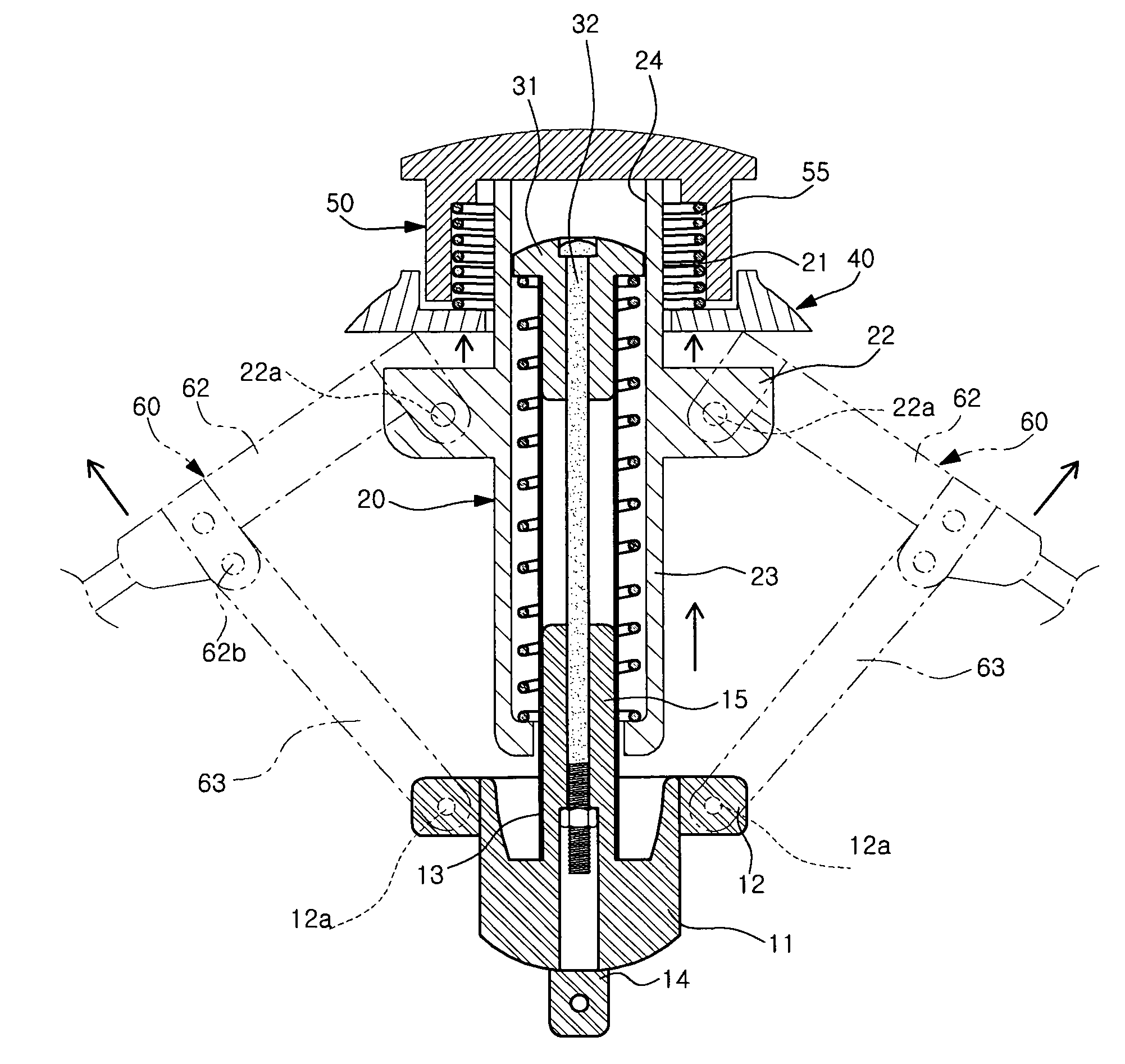
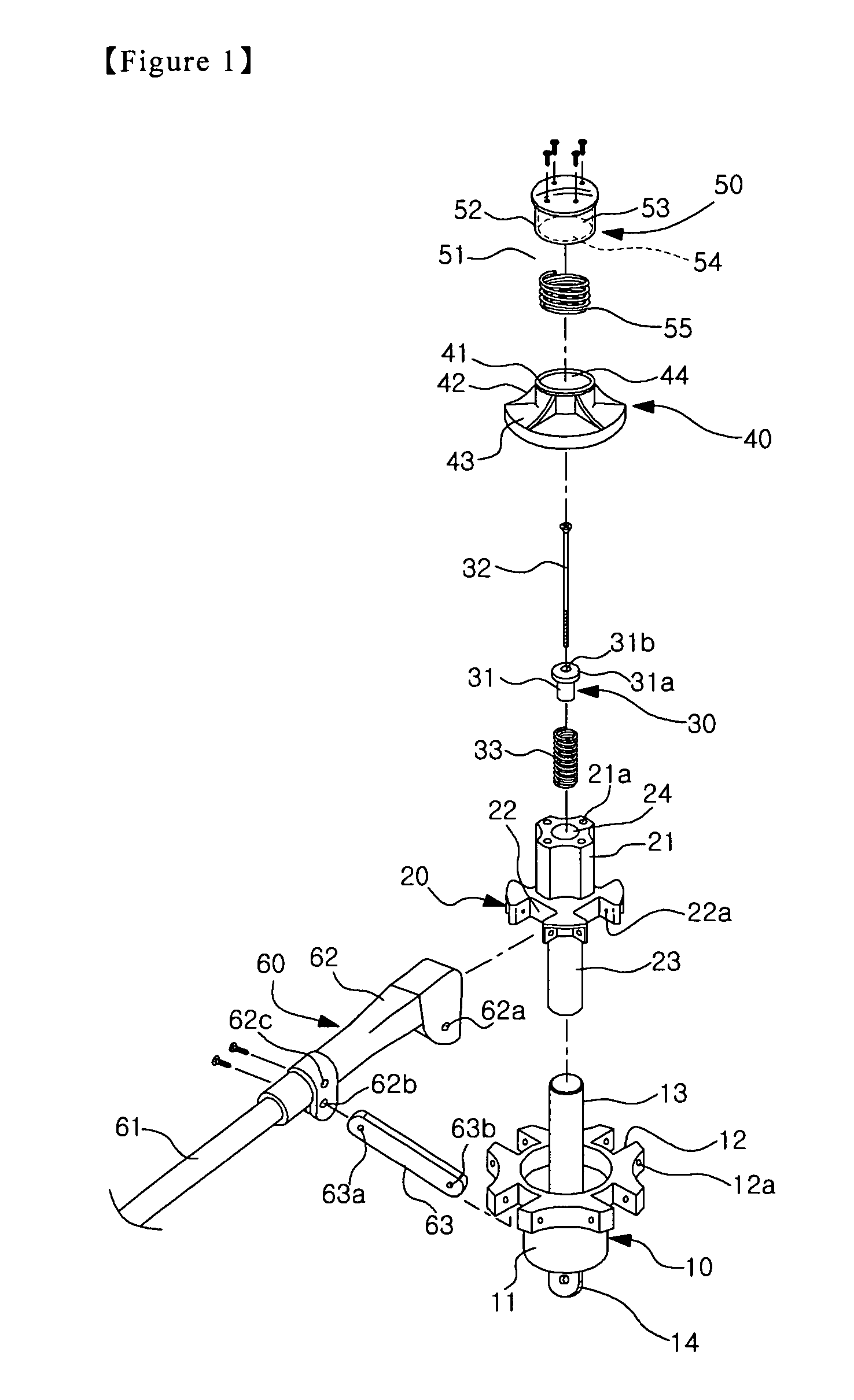
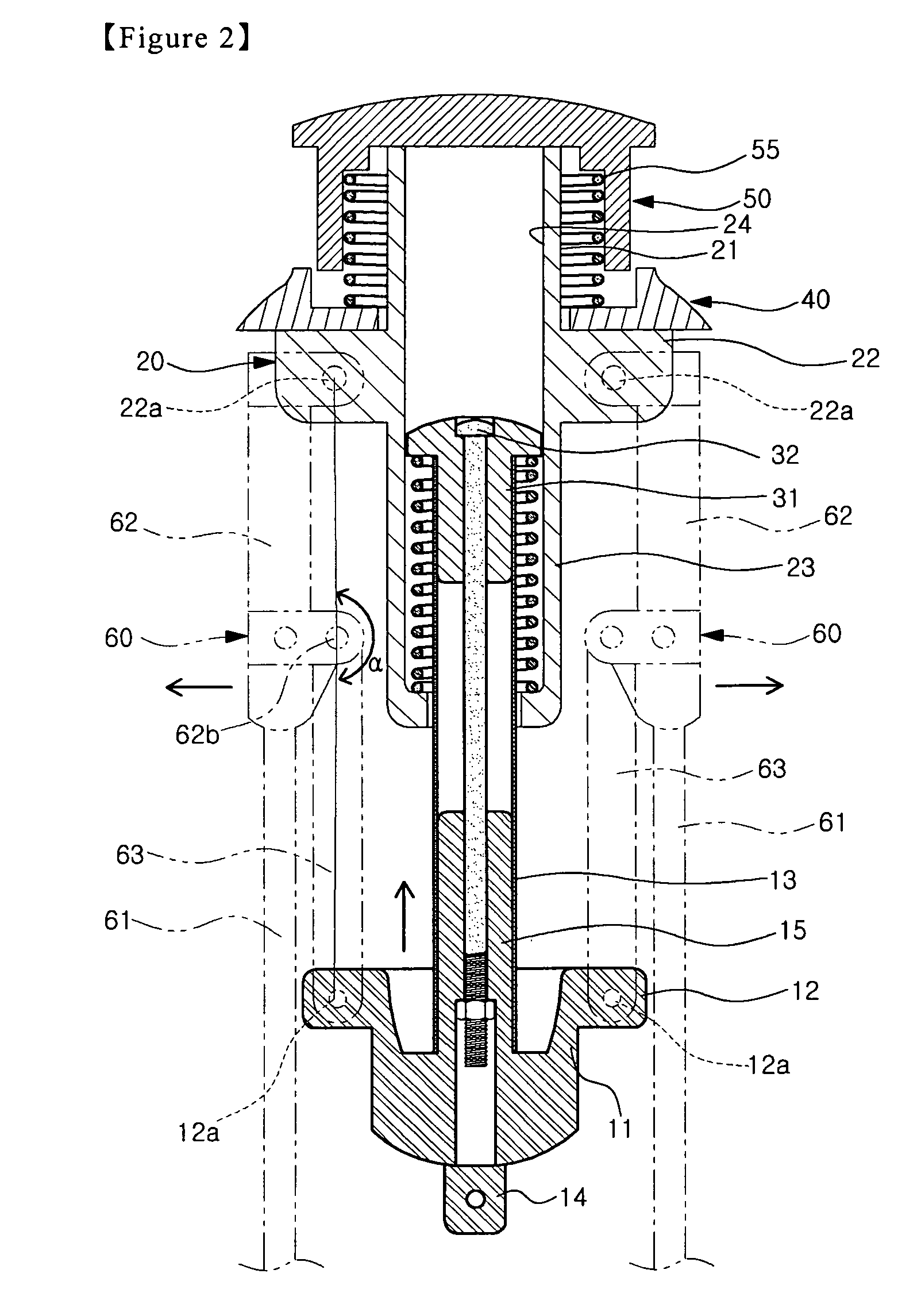
[0029]As shown in FIGS. 1 and 2, the frame assembly of the canopy tent of the present embodiment includes a sliding unit 10, a housing unit 20 in which the upper portion of the sliding unit 10 is slidably installed therein, a fixing unit 30 fixed to the top end of the sliding unit 10, a support unit 40 mounted on the housing unit 20, a cover unit 50 fixed to the top end of the housing unit 20, and upper connecting poles 60 and connecting units 63 to operatably connect the sliding unit 10 and the housing unit 20.

[0030]The sliding unit 10 includes a cylindrical portion 11, a plurality of engage slots 12, support tube 13, connector 14, and support rod 15.

[0031]More specially, the sliding unit 10 has a flange with the plurality of engage slots 12 formed therein, the cylindrical portion 11 making a lower body based on the flange, and the support tube 13 one end of which is inserted inside of the housing unit 20 and the other end of which is fixed to a support rod 15 extended upward from ...


PUM


Abstract

The present invention discloses a frame assembly for a canopy tent. The frame assembly includes a housing unit with a through hole formed therein, a sliding unit joined to the through hole, a fixing unit immovably joined to this sliding unit, a cover unit joined to the top of the housing unit, a support unit fitted into the outer circumference of said cover unit, an upper connecting pole in which a connecting socket pivotly connected to a engage slot is formed in the upper portion, and a connecting unit one end of which is pivotly connected to the connecting socket and the other end of which is pivotly connected to the sliding unit. Such a present invention provides effects that it is easy to install the canopy tent and it is possible to prevent a finger from being caught during operation thereof and safety accidents due to collision when the fixing unit comes off.

Description

[0001]This application claims priority to Korean Patent Application No. 2008-113353, filed on Nov. 14, 2008, in the Korean Intellectual Property Office, the entire contents of which are hereby incorporated by reference.BACKGROUND OF THE INVENTION[0002]1. Field of the Invention[0003]The present invention relates to a frame assembly for a canopy tent, more specifically to a canopy tent with an improved frame structure whereby it is possible to support the upper frame assembly for a canopy tent firmly and make it easy to install and dismantle the tent by making folding and unfolding easy.[0004]2. Description of the Related Art[0005]In general, of the various tents utilized in camping, etc., the canopy tent is widely used because it is quick and easy to install and dismantle it.[0006]Such a canopy tent can be said to be an automatic tent that has enhanced user's convenience, since installation and dismantling are completed in a short time just by putting the tent in the place to be inst...

Claims


Application Information

Patent Timeline
Patent Type & Authority Patents(United States)
IPC IPC(8): E04H15/28
CPCE04H15/28
Inventor HAN, JAE-KAB
Owner HAM DONG HWAN
Why Eureka
Try Eureka