Eureka AIR delivers breakthrough ideas for toughest innovation challenges, trusted by R&D personnel around the world.

Sheet conveying apparatus, image forming apparatus, and image scanning apparatus

a technology of conveying apparatus and sheet, which is applied in the direction of registering devices, thin material processing, article separation, etc., can solve the problems of large skew on sheets on which air was sprayed, affecting the accuracy of skew correction, and increasing the size of the whole apparatus, etc., and achieves the effect of accurate correction of skew and misalignment of various types of sheets and low cos

Active Publication Date: 2009-10-27
CANON KK
View PDF9 Cites 19 Cited by
  • Summary
  • Abstract
  • Description
  • Claims
  • Application Information

AI Technical Summary

Benefits of technology

[0024]To this end, the present invention provides a sheet conveying apparatus capable of accurately correcting the skew and misalignment of various types of sheet with an inexpensive configuration even in the event of reducing the apparatus in size.

Problems solved by technology

However, turning the conveying guide of a registration portion into a straight path leads in a problem wherein the whole apparatus increases in size.
The force differences with the force FLx and FRx applied at the time of correction increase simultaneously (Expressions (1) and (2)), which leads in a problem wherein skew correction accuracy is deteriorated by slip of the skew correction roller pair (Expression (3)).
Thus, various types of loaded sheet bundle can be separated and fed one at a time, but there is a possibility that the sheets on which air was sprayed are greatly skewed.
In addition to the velocity difference as to the conveying velocity VL and VR, the force difference as to the force FLx and FRx applied at the time of correction by the skew correction roller pair 1103a and 1103b also increases simultaneously (Expressions (1) and (2)), which leads in a problem wherein skew correction accuracy is deteriorated by slip of the skew correction roller pair (Expression (3)).

Method used


Image

  • Sheet conveying apparatus, image forming apparatus, and image scanning apparatus
  • Sheet conveying apparatus, image forming apparatus, and image scanning apparatus
  • Sheet conveying apparatus, image forming apparatus, and image scanning apparatus

Examples


first exemplary embodiment

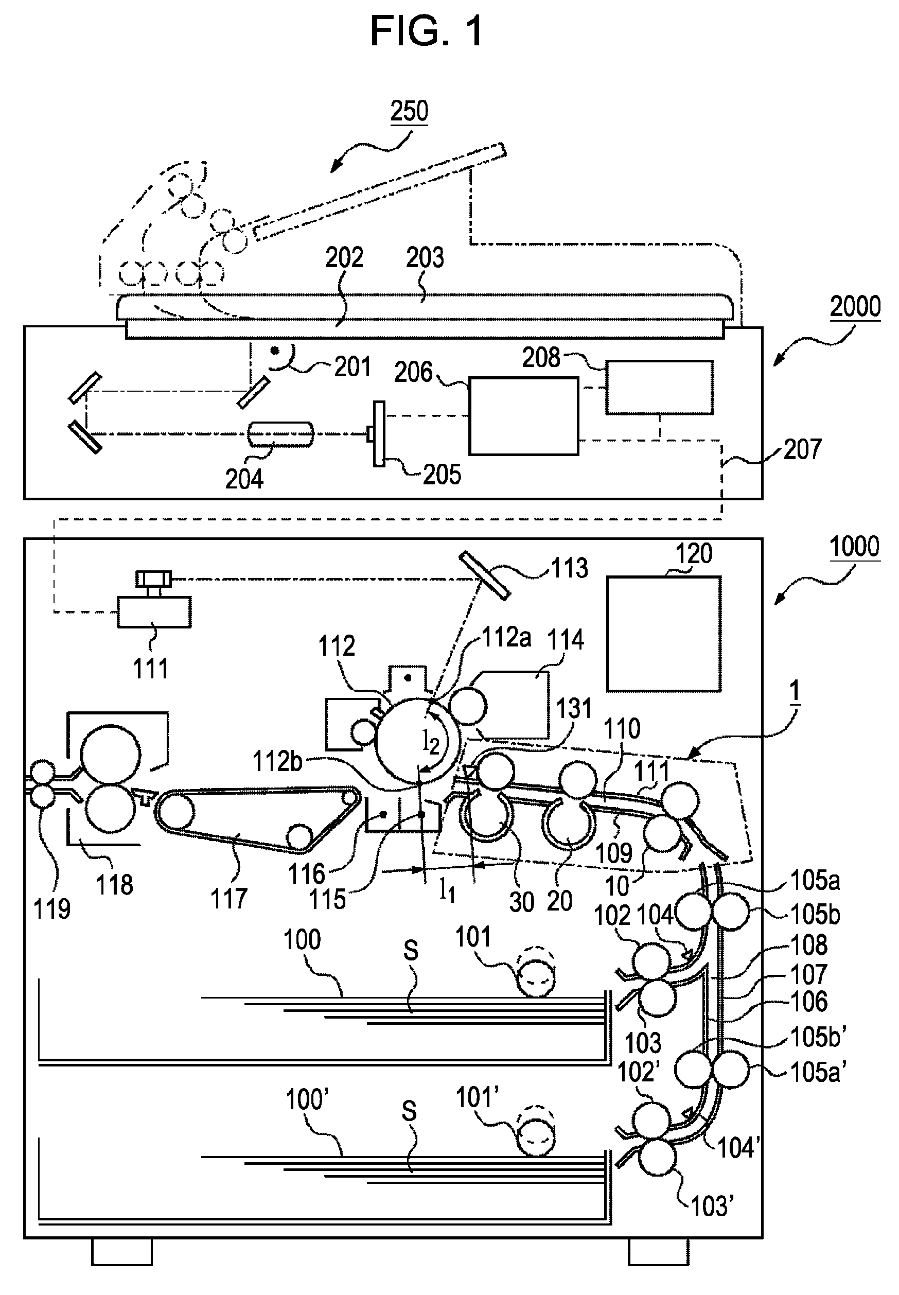
[0048]FIG. 1 is a cross-sectional view of a printer serving as an image forming apparatus to which a registration apparatus according to a first embodiment of the present invention is applied. In FIG. 1, reference numeral 1000 denotes a printer, 120 denotes a controller serving as a control unit configured to control the printer 1000. Reference numeral 100 is an upper cassette, sheets S stored in the upper cassette 100 are separated and fed one at a time by a sheet feeding unit made up of a pickup roller 101 configured to ascend / descend / rotate at predetermined timing, a feed roller 102, and a retard roller 103.

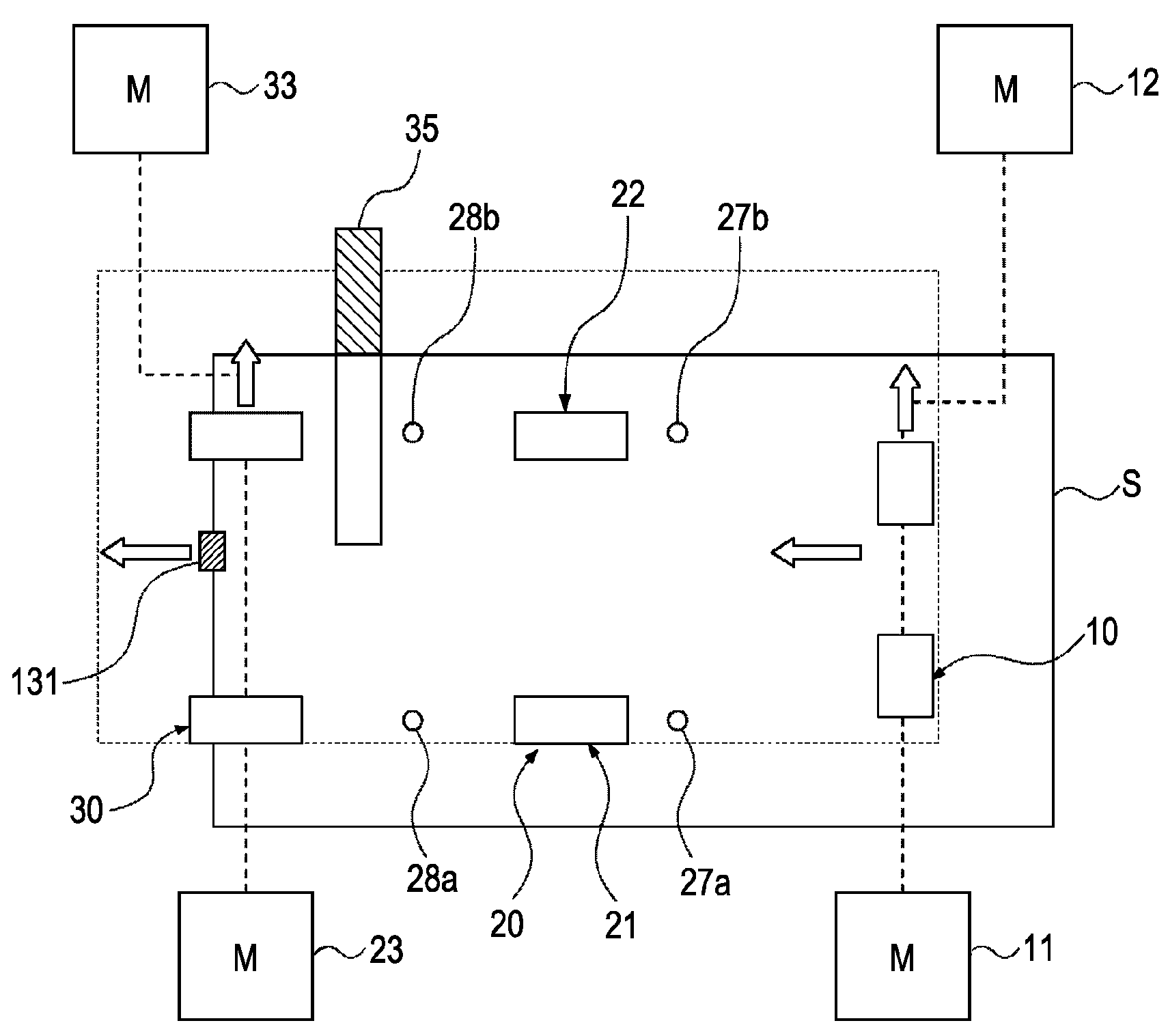
[0049]Subsequently, the sheet S fed from the sheet feeding unit is conveyed to a conveying path 108 made up of guide plates 106 and 107 by conveying roller pair 105a and 105b. The sheet S is conveyed to a registration portion 1 including a conveying path 110 where a bent conveying guide portion made up of guides 109 and 111 is disposed at the upstream side, an assistance rolle...

second exemplary embodiment

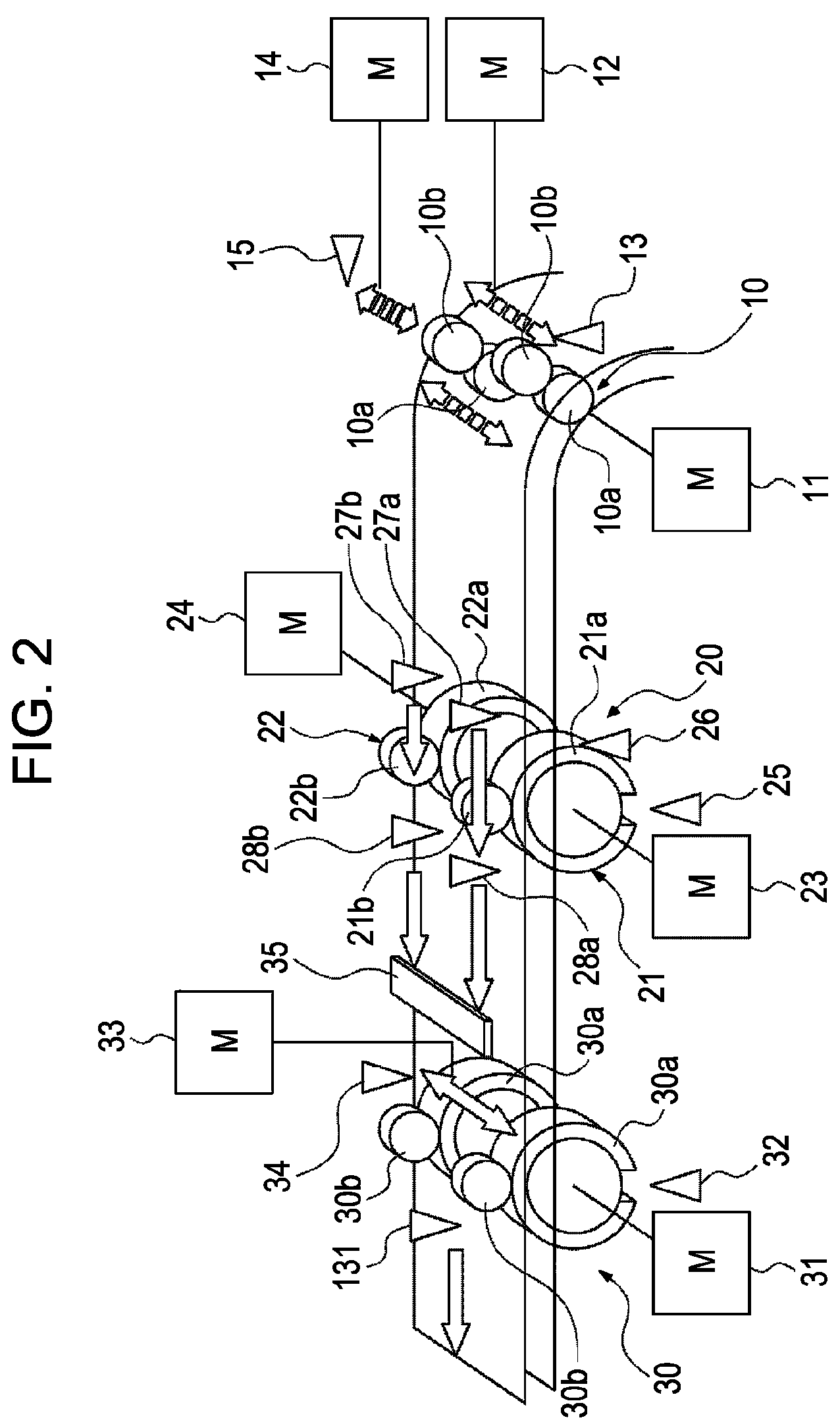
[0106]With the first embodiment, description has been made regarding the first roughly skew correction setting and the second high-precision skew correction setting by employing the driving control of the skew correction motors 23 and 24 and so forth. Now, description will be made regarding the first roughly skew correction setting and the second high-precision skew correction setting by employing the configurations of the skew correction roller pair 21 and 22 with reference to FIGS. 13 through 16. Note that apparatus configurations and control which will not be described below have the same as those in the first embodiment, so description thereof will be omitted.

[0107]FIG. 13 is a behavior schematic explanatory diagram between the skew correction roller pair 21 and 22, and the sheet S, wherein the sheet S is rotated in the ω direction, and is subjected to skew correction by the skew correction roller pair 21 and 22. At this time, the conveying force FL and FR from the correction ro...


PUM

PropertyMeasurementUnit
thicknessaaaaaaaaaa
sizeaaaaaaaaaa
conveying velocityaaaaaaaaaa

Abstract

A sheet conveying apparatus includes a skew correction unit configured to correct the skew of a sheet while conveying the sheet, controls the skew correction unit to correct the rough skew of the sheet by a first skew correction operation, and accurately correct the reduced skew of the sheet by a second skew correction operation.

Description

BACKGROUND OF THE INVENTION[0001]1. Field of the Invention[0002]The present invention relates to a sheet conveying apparatus to be included in an image forming apparatus such as a copier, a printer, a facsimile, and so forth, and an image scanning apparatus such as a scanner, and so forth.[0003]2. Description of the Related Art[0004]In recent years, with image forming apparatuses, there has been demand for high productivity (the number of sheets on which an image can be formed per unit time), and demand for reduction in size thereof, and also there has been increased demand for correcting skewing or misalignment of sheets with high precision, to improve image quality. Further, regarding thickness of sheets to be employed, it is necessary to convey thin paper to thick paper, small sizes such as a postcard to large size of 330 mm×488 mm or so regarding sizes, and further various types of paper such as coated paper, embossed paper, and so forth regarding paper type, in addition to plai...

Claims


Application Information

Patent Timeline
Patent Type & Authority Patents(United States)
IPC IPC(8): B65H7/02
CPCB65H9/002B65H2301/331B65H2404/14B65H2511/242B65H2513/20B65H2220/09B65H2220/01B65H2220/02B65H2511/24
Inventor INOUE, HIROSHIGE
Owner CANON KK
Why Eureka
Eureka Blog
Learn More