Optical image measuring apparatus

Inactive Publication Date: 2019-03-07
HITACHI LTD
View PDF8 Cites 2 Cited by
  • Summary
  • Abstract
  • Description
  • Claims
  • Application Information

AI Technical Summary

Benefits of technology

The patent describes a way to measure quickly by scanning the position of a light beam. This can be done using a component called a galvano mirror, which makes the light beam move. However, this makes the light beam longer and requires the reference light to also be longer, making the apparatus larger. The patent proposes using multiple light beams that create interference, which can be used to get a stable signal that is independent of any phase differences between the light beams. This results in a more accurate tomographic image of the measurement object.

Problems solved by technology

These light sources are more expensive than ordinary laser light sources that generate narrowband light.
From these facts, it is difficult to lower the price of the conventional OCT apparatus.
On the other hand, the measurement time tends to be long since it takes a long time to scan the condensing position.
As a result, the optical measuring apparatus becomes large.

Method used


Image

  • Optical image measuring apparatus
  • Optical image measuring apparatus
  • Optical image measuring apparatus

Examples


first embodiment

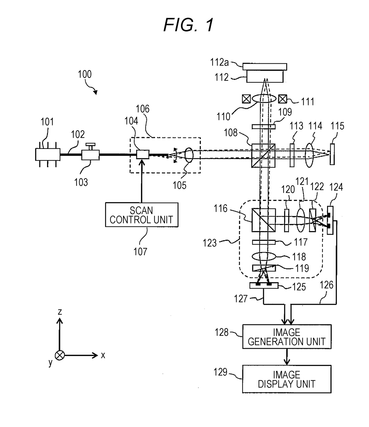
[0050]In the optical image measuring apparatus 100 according to the first embodiment, the fiber scanner 106 is disposed before the polarization beam splitter 108 branches the light into the signal light and the reference light, and the optical axis angle is scanned. In this configuration, unlike the case where the polarization beam splitter 108 branches the light into the signal light and the reference light, and then the fiber scanner 106 scans the optical axis angle of the signal light, the signal light reflected from the measurement object 112 is multiplexed with the reference light without propagating through an optical fiber (thus maintaining the wavefront information). Therefore, as described above, high z-resolution (spatial resolution in the optical axis direction) can be achieved.

[0051]In the optical image measuring apparatus 100 according to the first embodiment, an angular scanning element (not limited to a fiber scanner but a galvanometer mirror, a MEMS mirror, a polygon...

second embodiment

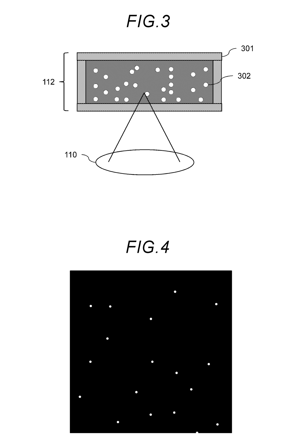
[0062]The optical image measuring apparatus 100 according to the second embodiment estimates the size of the particle 302 based on the reflection signal strength S. Thereby, the size of the particles 302 smaller than the spatial resolution of the optical image measuring apparatus 100 can be obtained.

third embodiment

[0063]FIG. 7 is a schematic diagram showing a configuration of an optical image measuring apparatus 100 according to a third embodiment of the present invention. The optical image measuring apparatus 100 according to the third embodiment includes three light sources 701, 702, and 703, each having a different wavelength, and an optical multiplexer 704, in place of the light source 101. Other configurations are the same as those in the first embodiment.

[0064]The light source 701, the light source 702, and the light source 703 respectively emit first laser light, second laser light, and third laser light having different wavelengths. Each laser light propagates through the optical fiber 102 and is guided to the optical multiplexer 704. The light sources 701 to 703 temporally alternately emit light with a repetition frequency higher than the driving frequency of the fiber scanner 106, and one of the light sources always emits light. More specifically, during a time when the fiber scanne...


PUM


Abstract

An optical image measuring apparatus according to the present invention includes an optical branching unit that branches light emitted from a light source into a signal light and a reference light, and an optical scanning unit that scans an angle of an optical axis emitted from the light source is disposed between the light source and the optical branching unit.

Description

CROSS-REFERENCE TO RELATED APPLICATION[0001]This application claims the priority of Japanese Patent Application No. 2017-171563 filed Sep. 6, 2017, which is incorporated herein by reference in its entirety.BACKGROUND OF THE INVENTION1. Field of the Invention[0002]The present invention relates to an optical image measuring apparatus for observing a measurement object using light.2. Description of the Related Art[0003]Optical coherence tomography (OCT) is a technique of acquiring a tomographic image of a measurement object by using light interference, and has been put into practical use since 1996 in the field of fundus examination. In recent years, the technique has been considered to be applied to various fields such as cardiology, dentistry, oncology, food industry and regenerative medicine.[0004]US2014 / 0204388 discloses a technique related to the OCT. As disclosed in the document, in the OCT, light from a light source is branched into two of signal light to be irradiated to a meas...

Claims


Application Information

Patent Timeline
IPC IPC(8): G01B9/02G01N15/02
CPCG01B9/02041G01B9/02091G01N15/0227G01N21/45
Inventor OSAWA, KENTARO
Owner HITACHI LTD
Why Eureka
Try Eureka