Vehicle heater control apparatus
a control apparatus and heater technology, applied in vehicle heating/cooling devices, power to electric heating circuits, vehicle components, etc., can solve the problems of increased cost, complicated control, and conventional technology, and achieve the effect of simple control and low cos
- Summary
- Abstract
- Description
- Claims
- Application Information
AI Technical Summary
Benefits of technology
Problems solved by technology
Method used
Image
Examples
first embodiment
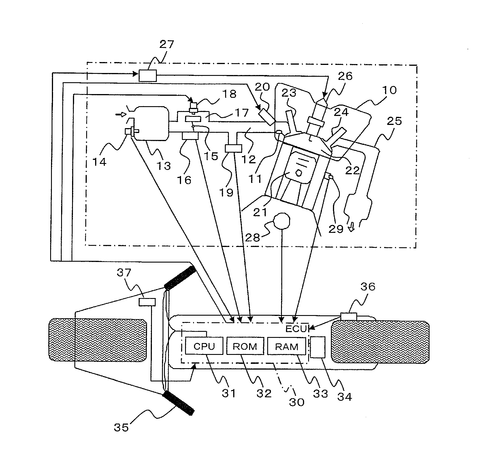
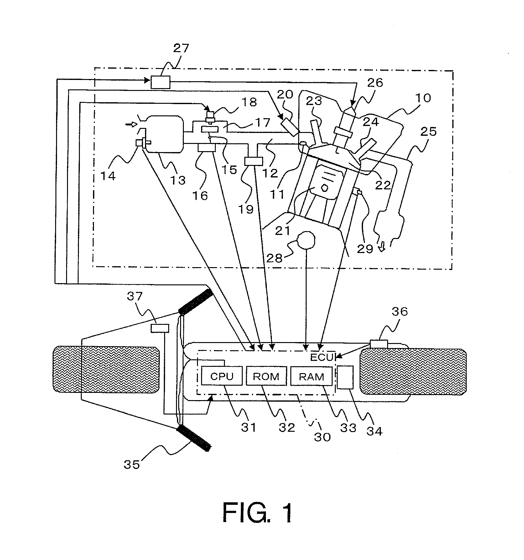
[0023]FIG. 1 is a configuration diagram illustrating the entire engine control system including a vehicle heater control apparatus according to a first embodiment of the present invention. In FIG. 1, an engine 10 includes an intake port 11 connected to an intake pipe 12. On an upstream side of the intake pipe 12, an air box 13 for sucking outside air is connected. Attached to the air box 13 is an intake air temperature sensor 14 (temperature detecting portion) for detecting the temperature of intake air.
[0024]Halfway through the intake pipe 12, there are provided a throttle valve 15 and a throttle position sensor 16 (throttle position detecting portion) for detecting a throttle position of the throttle valve 15. Further, in the intake pipe 12, a bypass air mechanical portion 17 is provided so as to sandwich the throttle valve 15. To the bypass air mechanical portion 17, an idle speed control (ISC) stepper motor 18 is provided.
[0025]Further, on a downstream side of the throttle valve...
PUM
 Abstract
Description
Claims
Application Information
 - R&D
- Intellectual Property
- Life Sciences
- Materials
- Tech Scout
- Unparalleled Data Quality
- Higher Quality Content
- 60% Fewer Hallucinations
Browse by: Latest US Patents, China's latest patents, Technical Efficacy Thesaurus, Application Domain, Technology Topic, Popular Technical Reports.
© 2025 PatSnap. All rights reserved.Legal|Privacy policy|Modern Slavery Act Transparency Statement|Sitemap|About US| Contact US: help@patsnap.com


