Eureka AIR delivers breakthrough ideas for toughest innovation challenges, trusted by R&D personnel around the world.

Ultrasound diagnostic apparatus and ultrasound image generating method

a diagnostic apparatus and ultrasound technology, applied in the field of ultrasonic diagnostic apparatus and ultrasound image generating method, can solve problems such as resolution and penetration, and achieve the effect of inexpensive configuration

Active Publication Date: 2020-05-28
KONICA MINOLTA INC
View PDF5 Cites 2 Cited by
  • Summary
  • Abstract
  • Description
  • Claims
  • Application Information

AI Technical Summary

Benefits of technology

[0008]In view of such circumstances, an object of the present invention is to provide an ultrasound diagnostic apparatus and an ultrasound image generating method that can provide clear ultrasound images with an inexpensive configuration.

Problems solved by technology

In a compact and inexpensive ultrasound diagnostic apparatus, the expensive transmission drive apparatus used in PTLs 1 to 3 cannot be adopted, which results in a compromise in terms of image quality such as resolution and penetration.

Method used


Image

  • Ultrasound diagnostic apparatus and ultrasound image generating method
  • Ultrasound diagnostic apparatus and ultrasound image generating method
  • Ultrasound diagnostic apparatus and ultrasound image generating method

Examples


first embodiment

[0036]The first embodiment of the present invention will be described below.

[0037][Outline of Each Component]

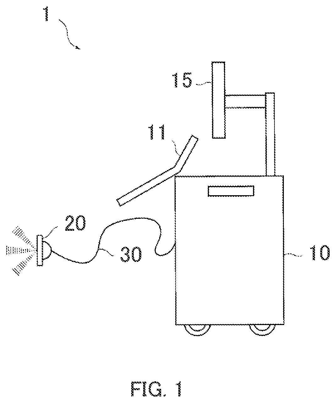
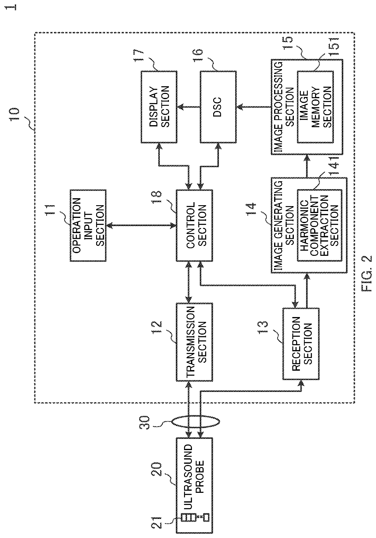
[0038]As shown in FIGS. 1 and 2, ultrasound diagnostic apparatus 1 according to the first embodiment includes ultrasound diagnostic apparatus body 10 and ultrasound probe 20. FIG. 1 is a diagram illustrating an external configuration of ultrasound diagnostic apparatus 1. FIG. 2 is a block diagram illustrating a functional component of ultrasound diagnostic apparatus 1 according to the first embodiment.

[0039]Ultrasound probe 20 transmits an ultrasound wave to a subject such as a living body (not shown) and receives a reflected wave (reflected ultrasound: echo) reflected by the subject.

[0040]Ultrasound diagnostic apparatus body 10 is connected to ultrasound probe 20 via cable 30, and transmits an electrical drive signal to ultrasound probe 20, thereby transmitting a transmission ultrasound wave to the subject. Further, Ultrasound diagnostic apparatus body 10 receives an electri...

second embodiment

[0094]The second embodiment of the present invention will be described below.

[0095][Outline of Each Component]

[0096]FIG. 7 is a block diagram illustrating the functional component of ultrasound diagnostic apparatus 1a according to the second embodiment.

[0097]In the following description, differences between ultrasound diagnostic apparatus 1a according to the second embodiment and ultrasound diagnostic apparatus 1 according to the first embodiment described above will be mainly described, and description of similar configurations will be omitted. In FIG. 7 and FIG. 8 to be described later, the components that operate differently from those in ultrasound diagnostic apparatus 1 according to the first embodiment are denoted by reference numerals with “a”.

[0098]In the second embodiment, transducers 21a of ultrasound probe 20a included in ultrasound diagnostic apparatus 1a are not cMUTs, but are transducers that output transmission sound pressure waveforms that are positive-negative symme...


PUM


Abstract

An ultrasound diagnostic apparatus of the present invention includes: a transmitter that generates and outputs a plurality of drive signals to a transducer of an ultrasound probe, the drive signals causing the transducer to transmit a plurality of transmission ultrasound waves that have different waveforms in a temporally shifted manner, the drive signals being compensated for asymmetry of the transmission sound pressure waveforms of the plurality of transmission ultrasound waves transmitted from the transducer; and a hardware processor configured to extract a harmonic component according to a plurality of reception signals, and generating an ultrasound image based on the extracted harmonic component.

Description

CROSS REFERENCE TO RELATED APPLICATIONS[0001]The entire disclosure of Japanese Patent Application No. 2018-219264 filed on Nov. 22, 2018, is incorporated herein by reference in its entirety.BACKGROUNDTechnological Field[0002]The present invention relates to an ultrasound diagnostic apparatus and an ultrasound image generating method that use ultrasound waves.Description of Related Art[0003]An ultrasound diagnostic apparatus is useful for repeated inspections because it can obtain heart beats and fetal movements in a real-time representation by a simple operation, that is, simply placing an ultrasound probe on a body surface, and is highly safe.[0004]Such an ultrasound diagnostic apparatus may in some cases be used with an imaging method for imaging a harmonic component (for example, frequencies 2f0, 3f0, and the like) of a reflected ultrasound wave (reception signal) with respect to a fundamental wave component (frequency f0) of a transmitted ultrasound wave. Such an imaging method ...

Claims


Application Information

Patent Timeline
Patent Type & Authority Applications(United States)
IPC IPC(8): A61B8/00B06B1/02A61B8/14A61B8/08G01S7/52
CPCB06B1/0292B06B2201/76G01S7/52077A61B8/4488B06B1/0215A61B8/5207A61B8/54A61B8/14A61B8/5269G01S7/52038G01S7/5202B06B2201/55G01S15/8963G01S15/8915B06B2201/51
Inventor TANIGUCHI, TETSUYA
Owner KONICA MINOLTA INC
Why Eureka
Eureka Blog
Learn More