Eureka AIR delivers breakthrough ideas for toughest innovation challenges, trusted by R&D personnel around the world.

Connector module and onboard camera using the same

a technology of connecting module and onboard camera, which is applied in the direction of television system, coupling device connection, transportation and packaging, etc., can solve the problems of increased manufacturing cost, uneven area of contact between the shield case and the shell of the plug, and uneven shielding effect. , to achieve the effect of maintaining shielding performance, water-proof performance, and minimizing deformation of the inner seal member

Active Publication Date: 2020-03-24
HOSIDEN CORP
View PDF26 Cites 3 Cited by
  • Summary
  • Abstract
  • Description
  • Claims
  • Application Information

AI Technical Summary

Benefits of technology

[0007]In view of this, there is desire for the provision of a connector module that has an inexpensive configuration and a high shielding ability.
[0023]In the above aspect, the annular projecting portion is formed in the straight linear portion of the central conductor, and the annular projecting portion is integrated with the insulator holder, thus reliably preventing the central conductor from coming out. Accordingly, the shielding effect of the conductive shell can be ensured over a long period of time.

Problems solved by technology

However, the technology disclosed in JP 2015-210292A has a risk of an increase in manufacturing cost due to the fact that the number of parts increases due to the use of a wave washer.
Also, the wave washer does not have a completely flat shape, and therefore the area of contact between the shield case and the shell of the plug is uneven, and there is a risk of degradation in the shielding effect.
Also, in the case where arm portions formed at the center of the bottom portion of the shield case are pressed by the leading end portion of the shell, if the position of the shield case becomes misaligned, the area of contact between the shield case and the shell of the plug becomes uneven, and there is a risk of degradation in the shielding effect.
If the engaging recession portion formed in the conductive shell is constituted by a through-hole, there is a risk that electromagnetic noise from the outside will intrude into the conductive shell through the through-hole and become included in the transmitted signal.

Method used


Image

  • Connector module and onboard camera using the same
  • Connector module and onboard camera using the same
  • Connector module and onboard camera using the same

Examples


Embodiment Construction

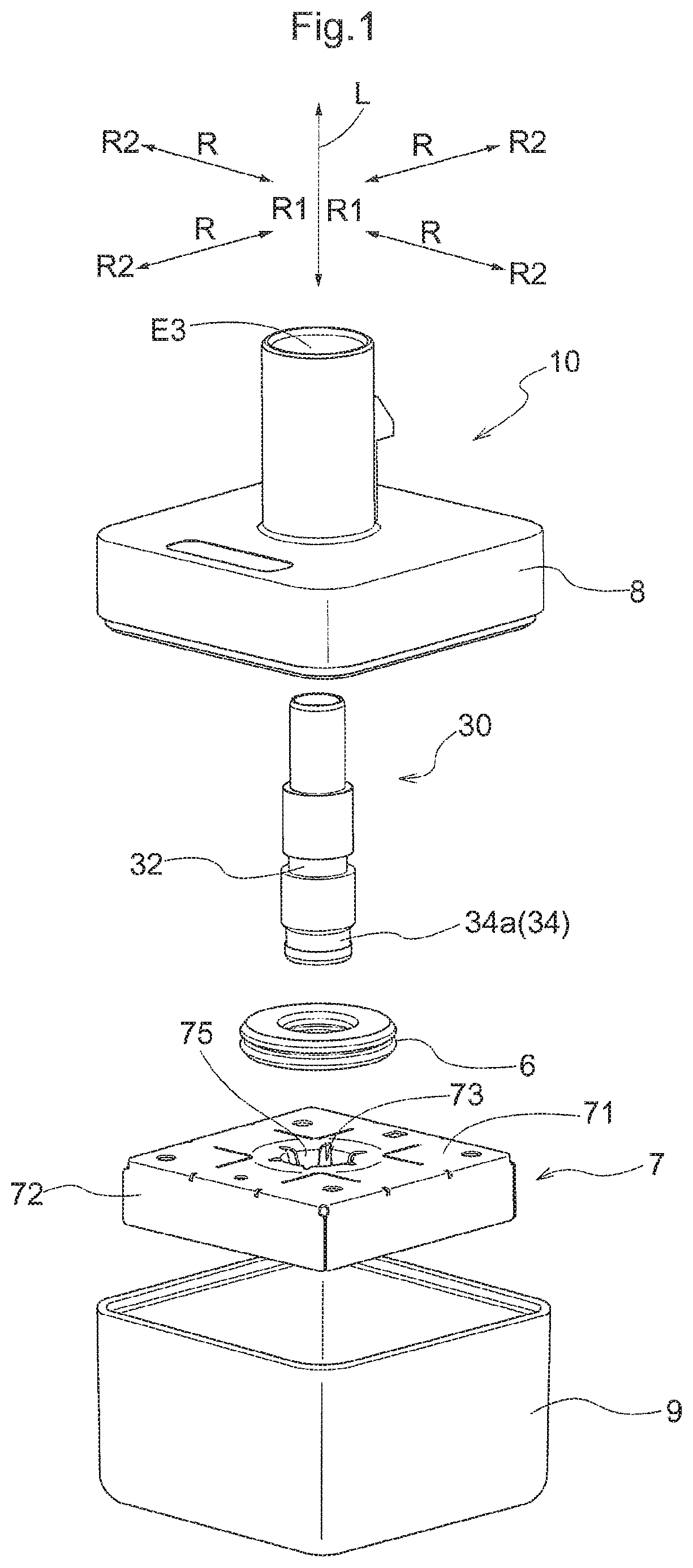
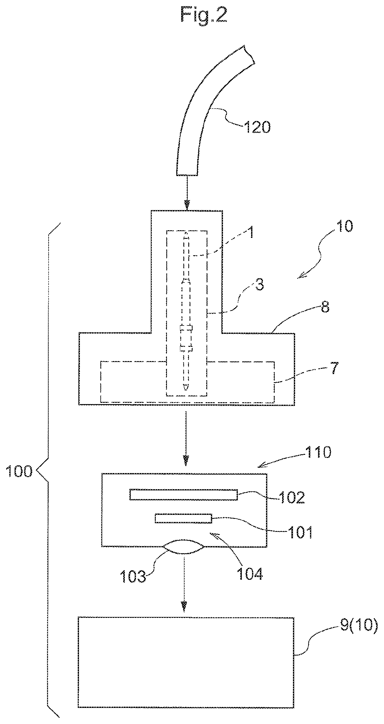
[0034]Hereinafter, an embodiment of a connector module 10 will be described with reference to the drawings. The present embodiment describes an example in which the connector module 10 is used in a camera unit 100 (onboard camera) that is for installation in a vehicle, as schematically shown in FIG. 2. This camera unit 100 can also be used in applications other than vehicle installation (e.g., installation in a bicycle, drone, or the like). The camera unit 100 has a camera module 110 and the connector module 10. The camera module 110 has at least an imaging element 101, an electronic circuit 102 that controls driving of the imaging element 101 and processes a video signal output from the imaging element 101, and an optical system 104 that includes a lens 103 for condensing light onto the imaging element 101.

[0035]The camera unit 100 is connected to an image processing device (not shown) or a monitor device (not shown) by a coaxial cable 120. The coaxial cable 120 is a cable having a...


PUM


Abstract

A connector module that has an inexpensive configuration and a high shielding ability is provided. The connector module includes a terminal module and a shield case. The terminal module has a central conductor, a tubular insulator holder that supports the central conductor, and a tubular conductive shell. A bottom portion of the shield case has multiple elastic portions that are capable of elastic deformation and are bent from and protrude from an edge portion of an opening portion for passage of the terminal module. The terminal module is joined to the shield case in a state where the annular recession portion of the conductive shell and the elastic portions are in electrical contact with each other.

Description

CROSS REFERENCE TO RELATED APPLICATION[0001]This application is based on and claims priority under 35 U.S.C. Section 119 to Japanese Patent Application No. 2017-192413 filed on Oct. 2, 2017 and Japanese Patent Application No. 2017-221728 filed on Nov. 17, 2017, the entire content of which are incorporated herein by reference.TECHNICAL FIELD[0002]This disclosure relates to a connector module that has a shield case, and also to an onboard camera that uses the connector module.RELATED ART[0003]JP 2015-210292A discloses a plug that is used for connecting a coaxial cable to a receptacle provided in an electronic circuit unit. The coaxial cable referred to here is a cable that has an internal conductor, an external conductor that surrounds the internal conductor and shields the internal conductor from electromagnetic noise, and a dielectric (insulator) that is arranged between the internal conductor and the external conductor.[0004]The plug includes an inner contact for connection with th...

Claims


Application Information

Patent Timeline
Patent Type & Authority Patents(United States)
IPC IPC(8): H01R24/54H01R13/6596H01R13/74H01R13/52H01R31/06H04N5/232H04N7/10H01R24/52H04N5/225H01R13/405H01R103/00
CPCH01R24/54H01R13/521H01R13/5202H01R13/6596H01R13/743H01R31/06H04N5/232H04N7/10H01R13/405H01R24/52H01R2103/00H04N5/2252H04N5/22521B60R11/04H01R13/426H01R13/502H01R13/6581H01R13/6591H01R2201/26H04N23/60H04N23/51H04N23/52
Inventor YAMAZAKI, MASAKAZU
Owner HOSIDEN CORP
Why Eureka
Eureka Blog
Learn More