Tray latching device

a latching device and tray technology, applied in the direction of passenger space, mechanical equipment, carpet fasteners, etc., can solve the problems of preventing and affecting the latching effect of the tray, so as to restrict the latching stroke and prevent the hook panel from being placed

a latching device and tray technology, applied in the direction of passenger space, mechanical equipment, carpet fasteners, etc., can solve the problems of preventing and affecting the latching effect of the tray, so as to restrict the latching stroke and prevent the hook panel from being placed

US7607703B2Inactive Publication Date: 2009-10-27HYUNDAI MOBIS CO LTD

Image

  • Tray latching device
  • Tray latching device
  • Tray latching device

Examples


Embodiment Construction

[0022]Now, a preferred embodiment of a tray latching device according to the present invention will be described with reference to the accompanying drawings.

[0023]The following embodiment is not intended to limit the scope of the present invention, rather, it is given for exemplary purposes, and various modifications, additions and substitutions are possible via a technical idea of the present invention.

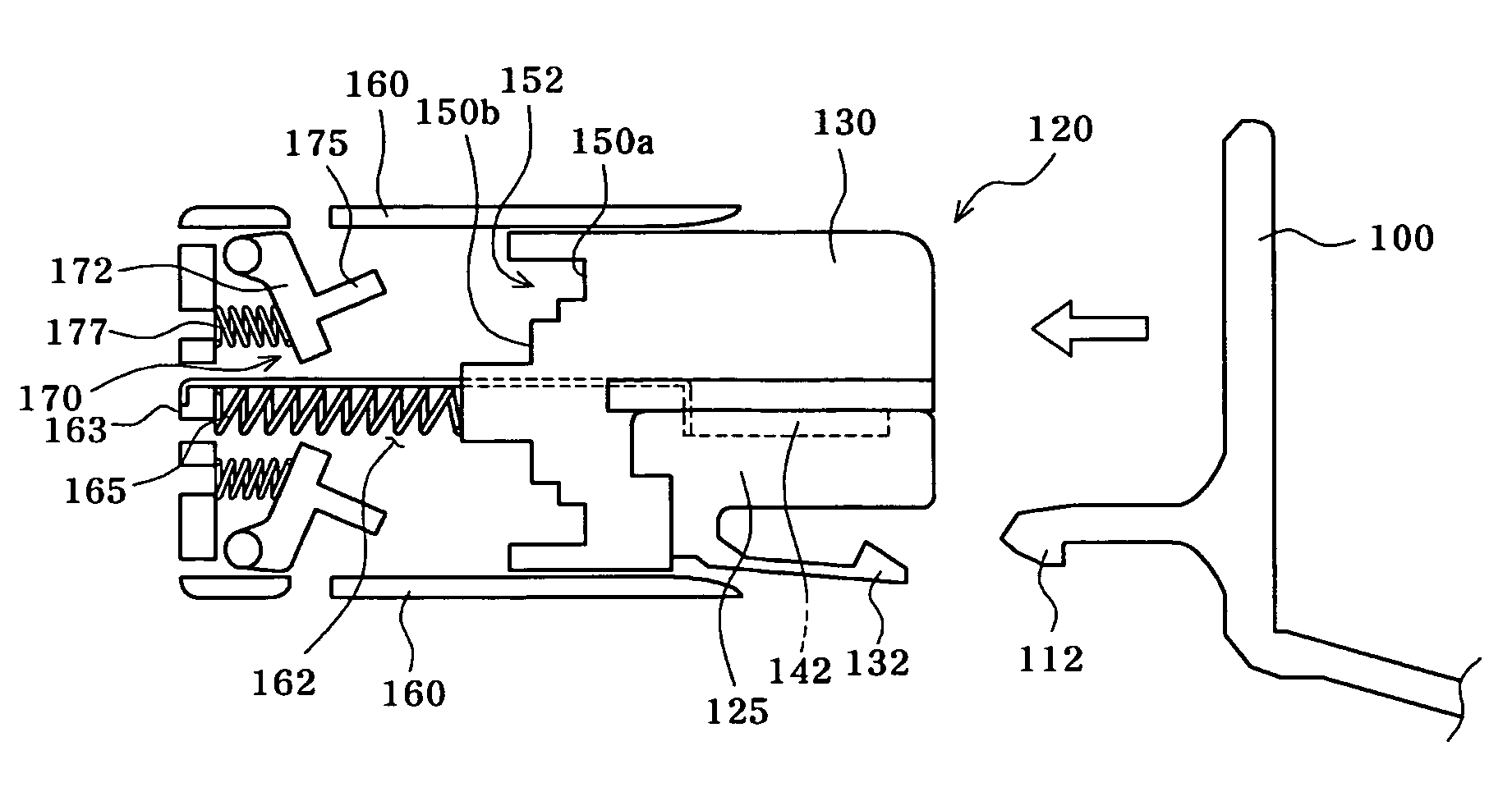
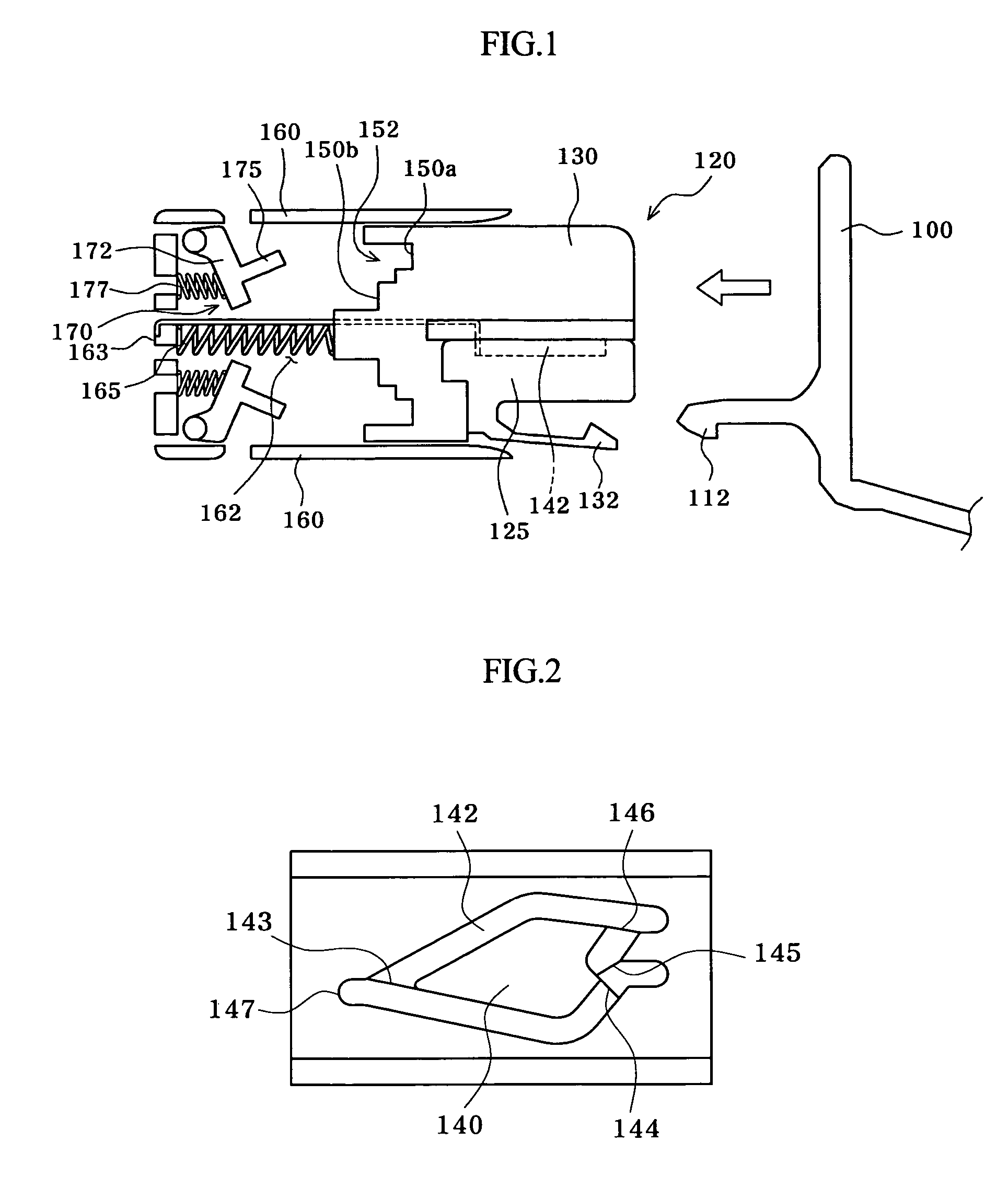
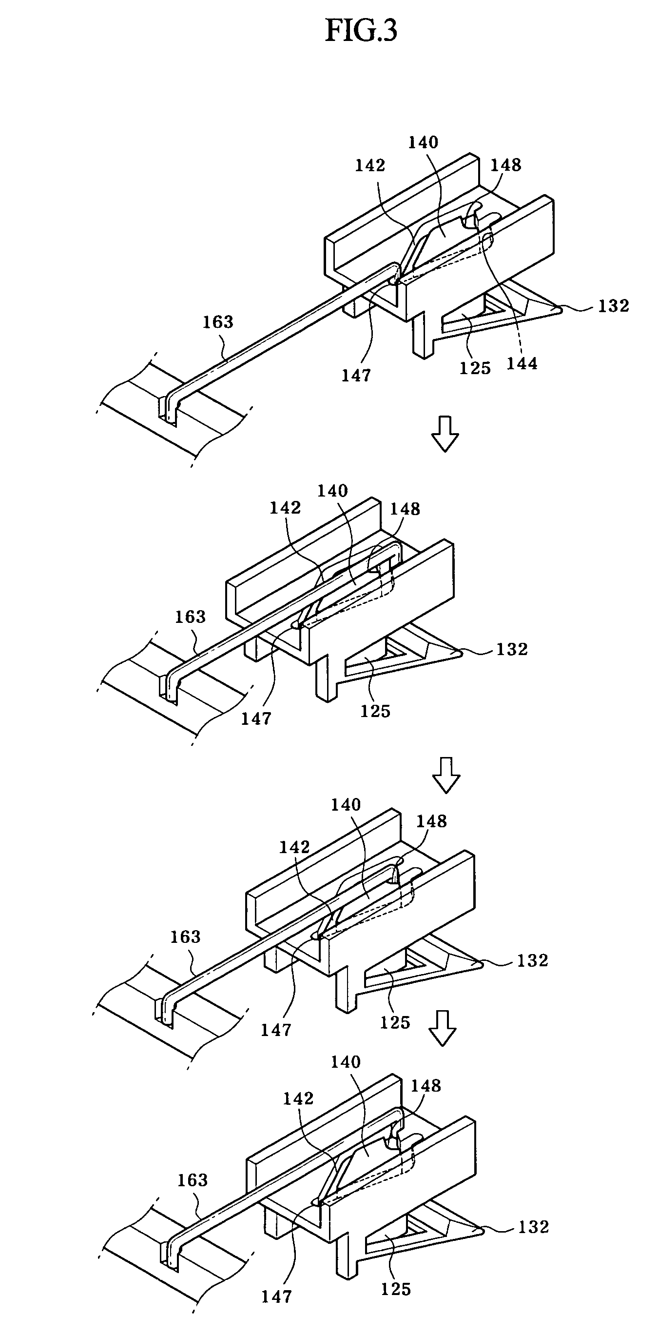
[0024]As shown in FIGS. 1 to 3, the tray latching device according to an embodiment of the present invention includes a latch 120 provided with a hook panel 132. The hook panel 132 catches the end of a clasp panel 112 that protrudes from a side of an automobile tray 100. The latch 120 is also provided therein with a heart cam 140. The heart cam 140 serves to release the clasp panel 112 of the tray 100 from the hook panel 132 when a predetermined stroke is applied to the clasp panel 112 via a pressure operation. Also, the latch 120 has a plurality of supporting indentations 152 each f...


PUM


Abstract

A tray latching device includes a latch including a hook panel to catch an end of a clasp panel that protrudes from a side of an automobile tray, a heart cam to release the clasp panel of the tray from the hook panel when a predetermined stroke is applied thereto by the clasp panel of the tray, and a plurality of supporting indentations each formed with a plurality of stepped supporting portions. The tray further includes a housing and a plurality of inertial sensors each including a supporting portion to be coupled to the housing via a shaft, and an extension that protrudes from the supporting portion to support an innermost supporting portion of one of the indentations of the latch.

Description

BACKGROUND OF THE INVENTION[0001]1. Field of the Invention[0002]The present invention relates to a tray latching device, and, more particularly, to a tray latching device for preventing an automobile tray, which is designed to be unlatched and opened when a predetermined stroke is applied thereto, from being unintentionally opened by an automobile collision, wherein a latch, which is formed with a plurality of supporting indentations having stepped supporting portions, is arranged at a side of the tray and a plurality of inertial sensors, which are adapted to rotate by collision inertia to suppress the stroke of the tray, is arranged at a side of the latch opposite to the tray, whereby, even in the case of rapid speed variation due to an automobile collision, unintentional opening of the tray can be prevented in accordance with operation of the inertial sensors.[0003]2. Description of the Related Art[0004]In general, an instrument panel of an automobile is provided with a dashboard ...

Claims


Application Information

Patent Timeline
27 Oct 2009
Publication
US7607703B2
IPC
E05C19/00; E05C1/08
CPC
E05C19/022; E05B77/06; Y10S292/04; Y10T292/096; Y10T292/0969; Y10T292/444; Y10T292/54; Y10T292/558
Inventors
CHO, JOUNG-HWAN