
Method of producing inkjet printhead

a printing head and inkjet technology, applied in printing, printed circuit manufacturing, variable capacitors, etc., can solve the problems of reducing the cost of materials, wasting the frame after the singulation of material sheets into individual laminates, and affecting the quality of materials, so as to reduce the cost of components, reduce the waste of materials, and eliminate waste of materials.

Inactive Publication Date: 2009-11-03
BROTHER KOGYO KK
View PDF10 Cites 2 Cited by
  • Summary
  • Abstract
  • Description
  • Claims
  • Application Information

AI Technical Summary

Benefits of technology

The invention provides a method of producing an inkjet printhead with a cavity unit having multiple kinds of plates. The method involves preparing a large-sized material sheet for each kind of plate, stacking the material sheets, and cutting the material sheet into individual plates. The method reduces waste material and produces less waste, resulting in lower costs. The invention also allows for the efficient use of material and produces a smaller printhead.

Problems solved by technology

In the conventional method, however, the frame left after the singulation of the laminate of the material sheets into the individual laminates is useless and discarded, involving some cost.
Further, due to the presence of the frame in the material sheet around the predetermined number of the plate regions, planar dimensions of the material sheet undesirably increase.

Method used


Image

  • Method of producing inkjet printhead
  • Method of producing inkjet printhead
  • Method of producing inkjet printhead

Examples


Embodiment Construction

[0027]Hereinafter, there will be described an inkjet printhead produced by a method according to one embodiment of the invention, by referring to FIGS. 1-8.

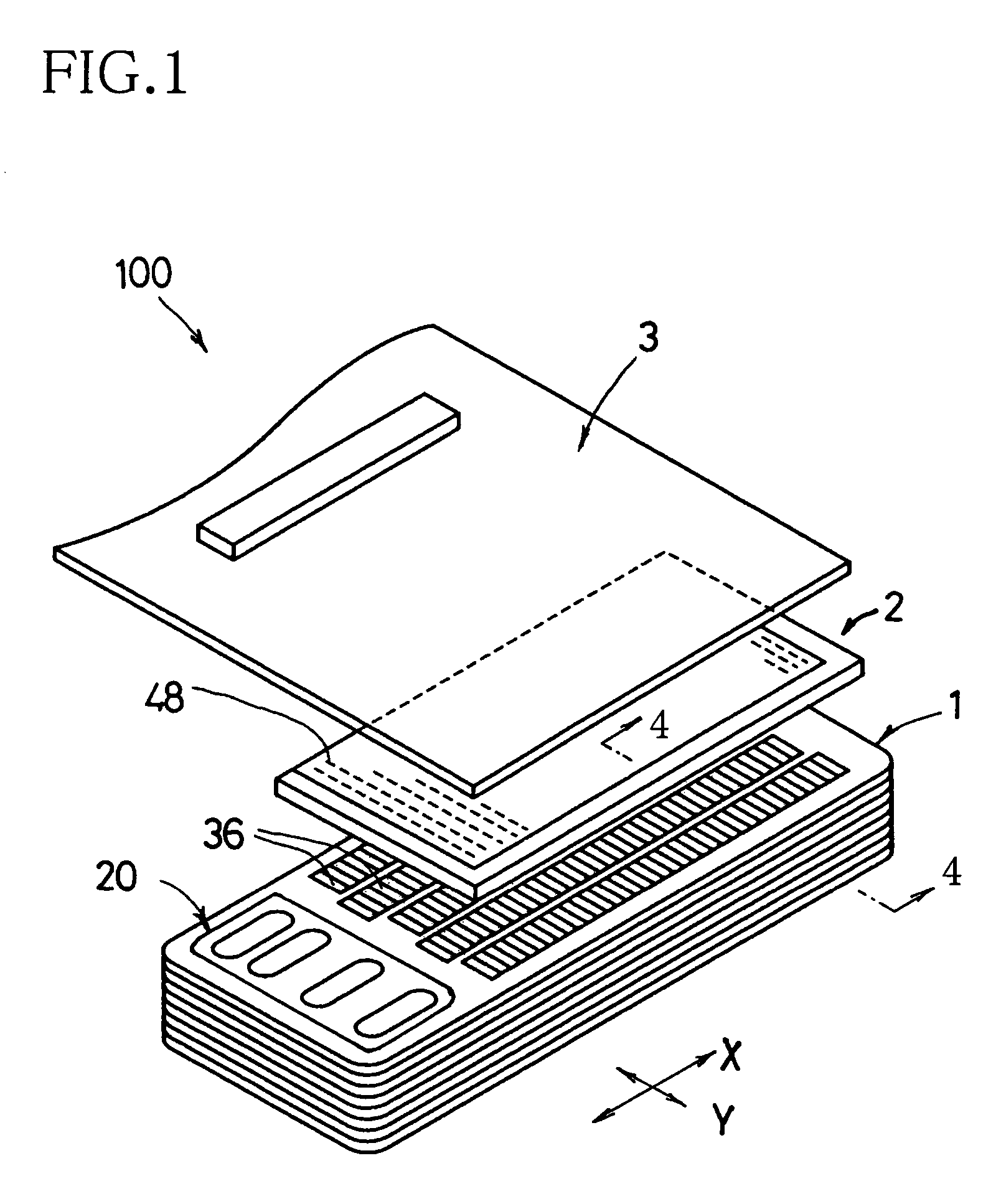
[0028]In FIG. 1, reference numeral 100 generally denotes a piezoelectric inkjet printhead produced by the method according to the embodiment. The inkjet printhead 100 has a cavity unit 1 including a plurality of plates, a planar piezoelectric actuator 2 fixed on the cavity unit 1, and a flexible flat cable 3 superposed on and fixed to an upper surface of the piezoelectric actuator 2, for connection with an external device. The cavity unit 1 has nozzles 4 open in an under surface of the cavity unit 1 to therefrom eject ink droplets downward, as shown in FIG. 4.

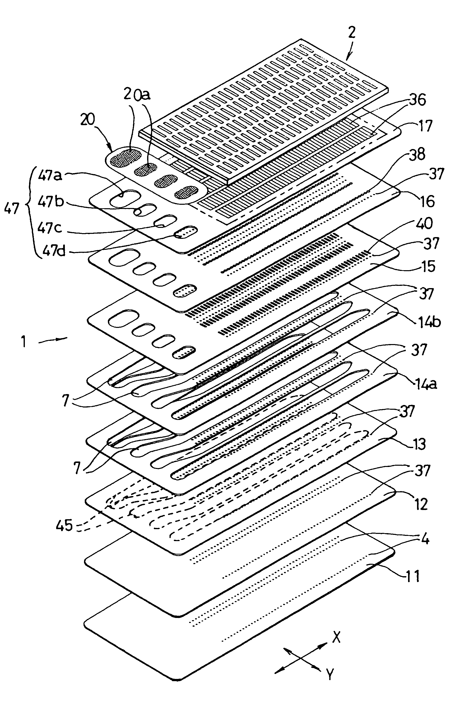
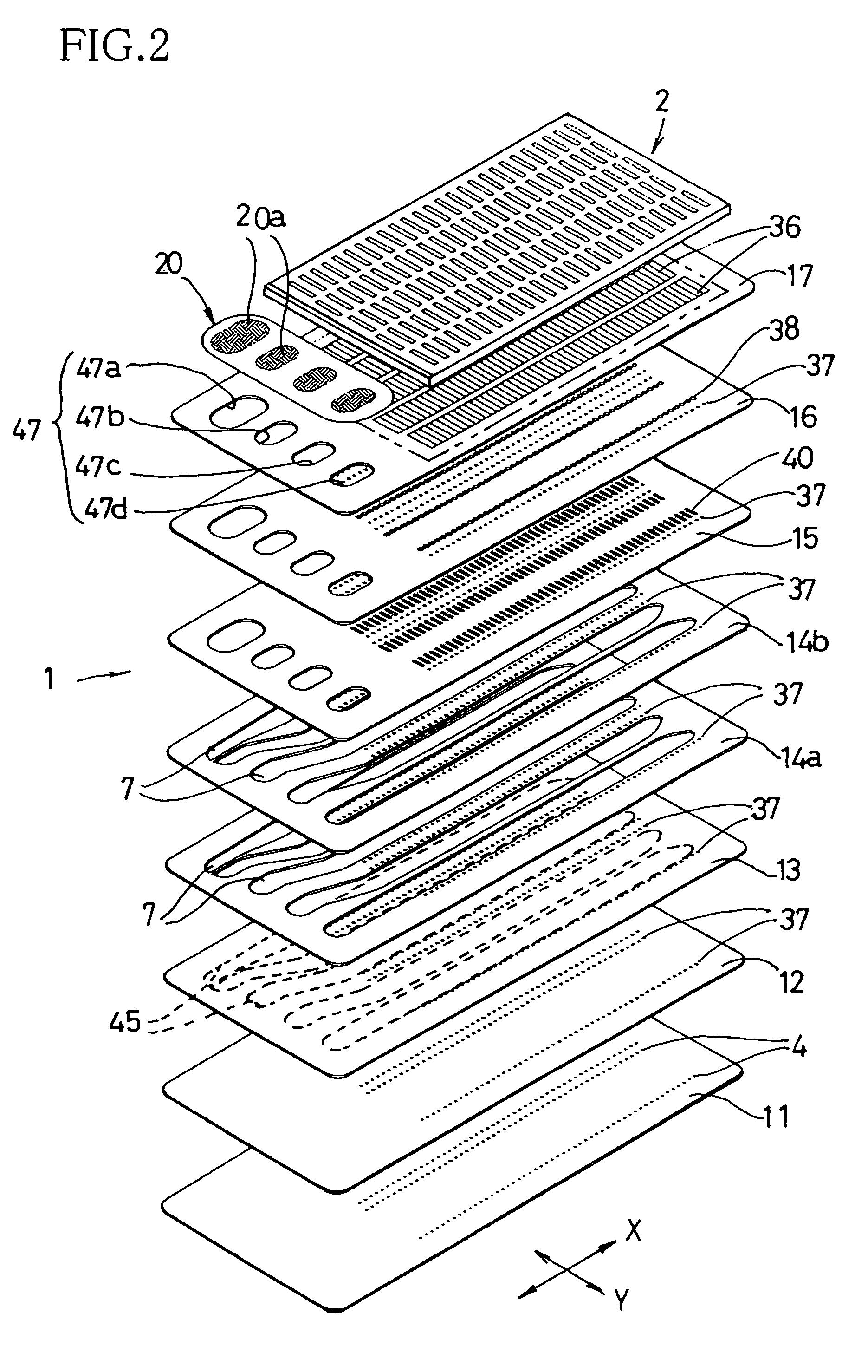
[0029]There will be described a structure of the cavity unit 1. As shown in FIG. 2, the cavity unit 1 is formed by stacking and bonding with an adhesive eight thin plates, namely, a nozzle plate 11, a pacer plate 12, a damper plate 13, two manifold plates 14a, 14b, a supply ...


PUM

PropertyMeasurementUnit
diameteraaaaaaaaaa
thicknessaaaaaaaaaa
shapeaaaaaaaaaa

Abstract

There is disclosed a method of producing an inkjet printhead including a cavity unit having therein ink passages and formed by stacking a plurality of kinds of flat plates each of which has a specific ink-passage pattern for constituting the ink passages. The method comprises: preparing a large-sized material sheet for each kind of a plate, such that the material sheet comprises a plurality of plate regions, each of which corresponds to one individual plate of the kind, and which are contiguous to one another such that a reserved region for cutting is between each adjacent two plate regions and there is left no margin at a periphery of the material sheet; obtaining a laminate of the material sheets by stacking the material sheets of respective kinds of plates, with the corresponding plates in the respective material sheets aligned in a direction of stacking of the material sheets; and obtaining a plurality of individual laminates by cutting the laminate of the material sheets at the reserved region into the individual laminates.

Description

INCORPORATION BY REFERENCE[0001]The present application is based on Japanese Patent Application No. 2004-327214, filed on Nov. 11, 2004, the content of which is incorporated herein by reference.BACKGROUND OF THE INVENTION[0002]1. Field of the Invention[0003]The invention relates to a method of producing an inkjet printhead applicable to an image recording apparatus that records information on a recording medium by ejecting ink droplets from nozzles.[0004]2. Description of Related Art[0005]As disclosed in JP-A-2002-105410 (especially FIG. 10) by the present applicant, for instance, there is known a method of producing an inkjet printhead including a cavity unit, a piezoelectric actuator, and a flexible flat cable. The cavity unit has in a front surface thereof a plurality of nozzles arranged in rows, and ink passages for supplying ink as drawn from an ink supply source to the nozzles. The piezoelectric actuator has active portions so as to selectively eject an ink droplet from each n...

Claims


Application Information

Patent Timeline
Patent Type & Authority Patents(United States)
IPC IPC(8): B23P17/00B41J2/045
CPCB41J2/1609B41J2/1623B41J2/1629B41J2/1632B41J2/1634B41J2/1635Y10T29/49128Y10T29/49135Y10T29/49401Y10T29/435Y10T29/4913Y10T29/49126
Inventor ITO, ATSUSHI
Owner BROTHER KOGYO KK
Learn More