Eureka AIR delivers breakthrough ideas for toughest innovation challenges, trusted by R&D personnel around the world.
Jacquard machine
What is Al technical title?
Al technical title is built by PatSnap Al team. It summarizes the technical point description of the patent document.
a technology of jacquard and guide rod, which is applied in the field of jacquard machines, can solve the problems of increasing the cost of maintenance, affecting the service life of the guide rod, and the height required to install it to be large, and achieves the effect of similar stiffness and similar stiffness
Active Publication Date: 2009-11-03
VAN DE WIELE MICHEL
View PDF10 Cites 2 Cited by
Summary
Abstract
Description
Claims
Application Information
AI Technical Summary
This helps you quickly interpret patents by identifying the three key elements:
Problems solved by technology
Method used
Benefits of technology
[0016]In this manner, a Jacquard machine is obtained having a reduced number of components and a restricted number of hinge points.
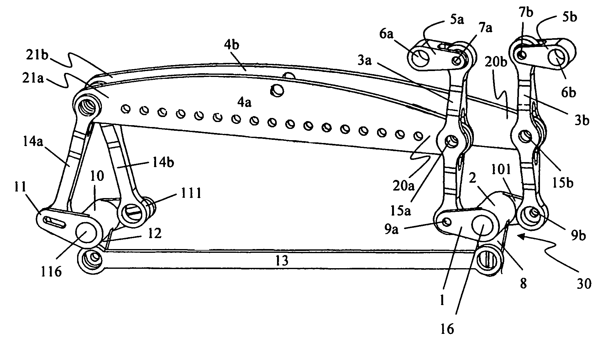
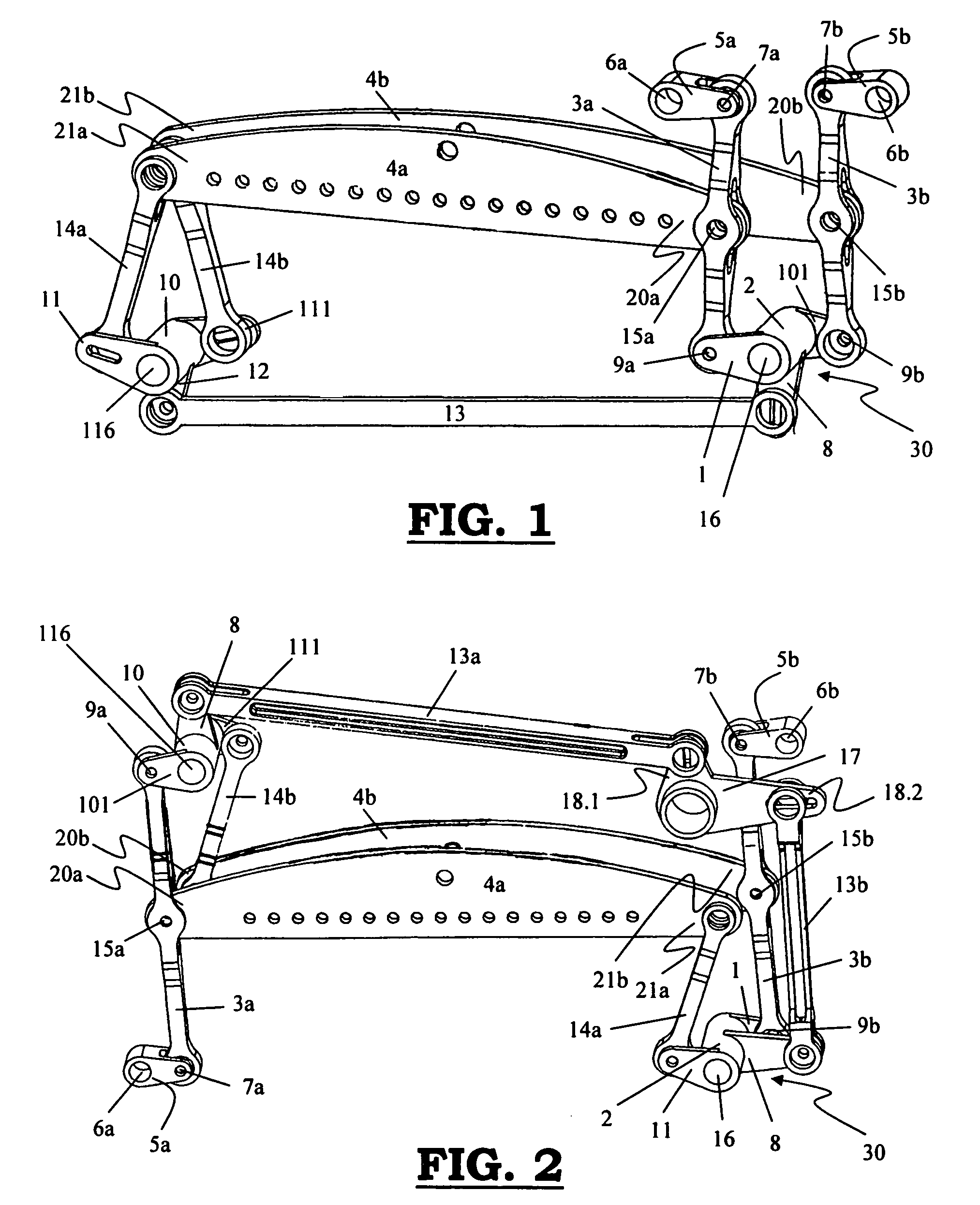
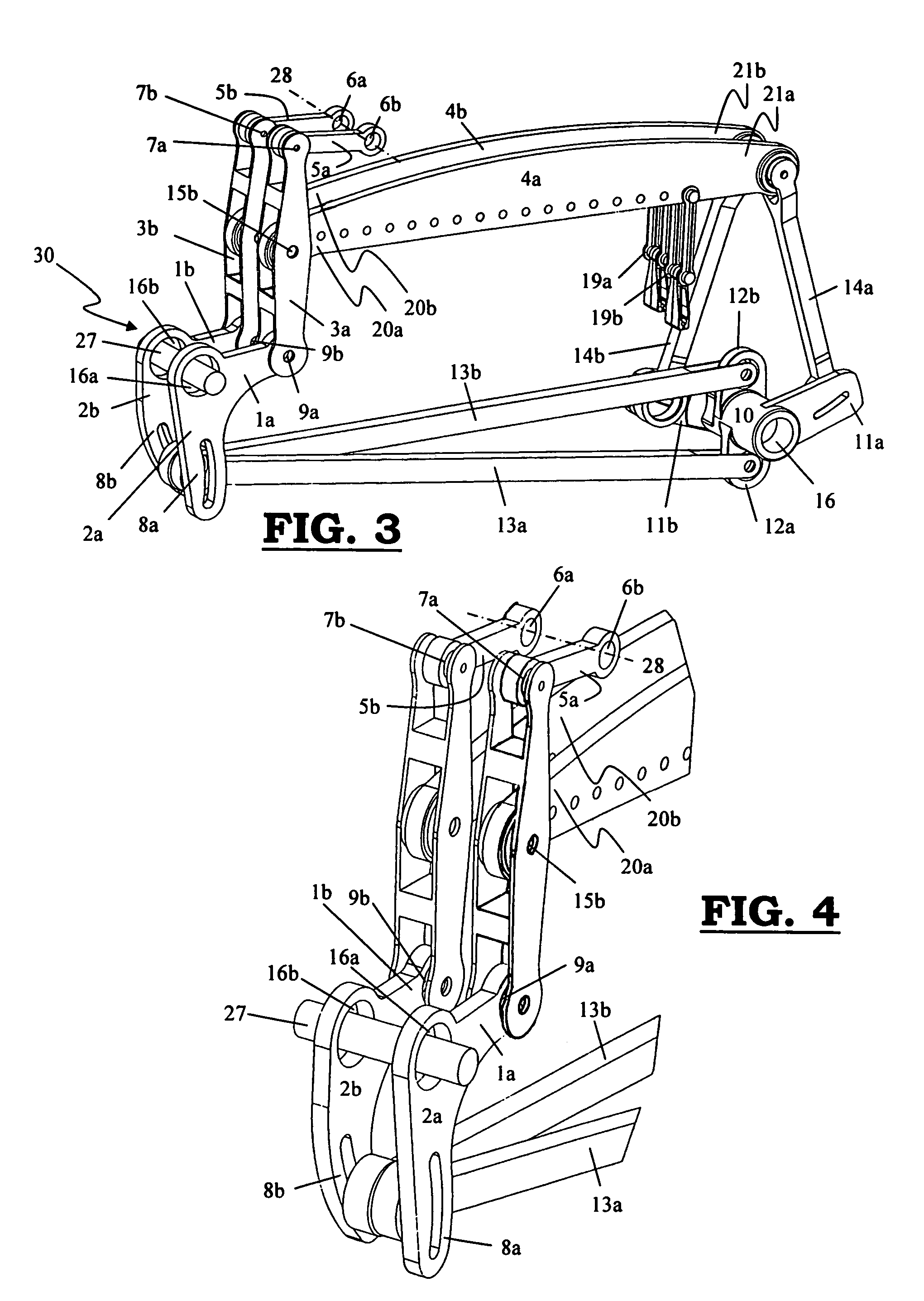
[0027]Preferably, the hinge points about which the first driving levers are rocking, are situated here in one line on the same axis, such that the hinge points of the Watt's linkage is situated in one line on the same axis. By providing the adjustability of the stroke in the two additional lever arms of the first driving levers (not being part of the Watt's linkage), it will be possible to adjust the stroke separately for both knife grids. With this more preferred embodiment it will be possible to dimension the knife grids equally large, such that both knife grids will have the same stiffness.
[0028]In the first, second and third preferred embodiment of a Jacquard machine according to the invention, the two Watt's linkage rod systems may be coupled to two different driving levers, to the same or to a different extremity of the knife grids, allowing both knife grids to be made equal as to length, and for both knife sets to obtain a similar stiffness.
Problems solved by technology
Such guides, however, are strongly subject to wear.
Moreover, the knife grids situated one above the other will cause the height required to install them to be great.
This way of installing is already more compact as to height than is the case in the one shown in EP 136 244, but also here, the guiding components will cause wear, thus increasing the cost for maintenance and it is no guarantee for a permanent good performance of the Jacquard machine.
The guiding slots are a disadvantage, because there is quite some significant material contact, causing friction and developing heat and the components will be subject to wear.
At high speeds, these effects are very disadvantageously increased.
However, the longer the motion of the knife grid, the greater the deviation with respect to the vertical motion.
However, the longer the rod, the smaller the deviation, but the more expensive the part and the greater the inertia.
For larger Jacquard machines, additional slots are provided at the left and right, having the known disadvantages as far as wear and maintenance costs are concerned.
Because of this, wear remains within bounds.
However, 3 additional rods and 5 additional linking points with bearings are added per knife grid, considerably increasing both the inertia and the price of the Jacquard machine.
Method used
Image
Click on the blue label to locate the original text in one second.
Reading with bidirectional positioning of images and text.
Examples
Embodiment Construction
[0036]A Jacquard machine according to the invention comprises two sets of knifes moving up and down in opposition, which each, at their extremities, are taken up in separate knife grids (4a, 4b), which are driven by a cinematic drive chain (30) and which each at one of their extremities (20a, 20b) are guided into a straight motion by means of a “Watt's linkage” rod system. The height of lift of each of these extremities (20a, 20b) of the knife grids (4a, 4b) (=stroke) being adjustable. The knife grids (4a, 4b) each at their first extremities (20a, 20b), being linked with at least a first driving lever (2, 2a, 2b, 10) by means of a first linking rod (3a, 3b), and at their second extremities (21a, 21b) are linked with at least a second driving lever (2, 10) by means of a second linking rod (14a, 14b). Per knife grid (4a, 4b), one or several elements (1, 101, 1a, 1b, 3a, 3b) of the Watt's linkage rod system are part of the cinematic drive chain (30). Moreover, the amplitude of the moti...
PUM
Abstract
The invention relates to a Jacquard machine, comprising 2 sets of knifes moving up and down in opposition, which each, at each of their extremities, are taken up in separate knife grids (4a, 4b) being driven by a cinematic drive chain (30), and each, at one of their extremities (20a, 20b), being guided into a straight motion by means of a “Watt's linkage” rod system, the height of lift of each of these extremities (20a, 20b) of the knife grids (4a, 4b) being adjustable, and the knife grids (4a, 4b) each at their first extremities (20a, 20b) being linked with at least one first driving lever (2, 2a, 2b, 10) by means of a first linking rod (3a, 3b), and at their second extremities (21a, 21b) being linked with at least a second driving lever (2, 10) by means of a second linking rod (14a, 14b), wherein per knife grid (4a, 4b) one or several elements (1, 101, 1a, 1b, 3a, 3b) of the Watt's linkage rod system are part of the cinematic drive chain (30), and the amplitude of the motion of the said extremity (20a, 20b) of the knife grid (4a, 4b) is adjustable in the cinematic drive chain (30) before the linking point (9a, 9b) between the first rod (1, 101, 1a, 1b) and the third rod (3a, 3b) of the Watt's linkage rod system with respect to the drive motor.
Description
[0001]This application claims the benefit of Belgian Application No. 2005 / 0185 filed Apr. 8, 2005.BACKGROUND OF THE INVENTION[0002]The invention relates to a Jacquard machine, comprising 2 sets of knifes moving up and down in opposition, which each, at their extremities, are taken up in separate knife grids being driven by a cinematic drive chain, and each, at one of their extremities, being guided into a straight motion by means of a “Watt's linkage” rod system, the height of lift of each of these extremities of the knife grids being adjustable, and the knife grids each at their first extremities being linked with at least one first driving lever by means of a first linking rod, and at their second extremities being linked with at least a second driving lever by means of a second linking rod.[0003]The construction of Jacquard machines is subjected to an ever increasing pressure to produce machine at lower prices and operating faster, that are sufficiently strong to realize the form...
Claims
Application Information
Patent Timeline
Application Date:The date an application was filed.
Publication Date:The date a patent or application was officially published.
First Publication Date:The earliest publication date of a patent with the same application number.
Issue Date:Publication date of the patent grant document.
PCT Entry Date:The Entry date of PCT National Phase.
Estimated Expiry Date:The statutory expiry date of a patent right according to the Patent Law, and it is the longest term of protection that the patent right can achieve without the termination of the patent right due to other reasons(Term extension factor has been taken into account ).
Invalid Date:Actual expiry date is based on effective date or publication date of legal transaction data of invalid patent.
Patent Type & Authority Patents(United States)
IPC IPC(8): D03C3/24D03C3/32D03C3/00
CPCD03C3/36
Inventor VANDERJEUGT, BRAMTHEOBALD, MATTHEWGRAHAM, JAMES ANTHONY