Fusible link

a technology of fusing circuit and fusing link, which is applied in the direction of basic electric elements, emergency protective devices, electrical equipment, etc., can solve the problems of large depth housing, inability to achieve compact fusing links, and inability to reach the fusing circuit to come clos

Active Publication Date: 2009-11-03
YAZAKI CORP
View PDF18 Cites 25 Cited by
  • Summary
  • Abstract
  • Description
  • Claims
  • Application Information

AI Technical Summary

Benefits of technology

[0013]Hence, an object of the invention is to provide a fusing link having a compact design. The fusing link has a fuse circuit with a fusible portion that operates stably to provide an appropriate fusing time.
[0022]Thus, even when the housing is horizontally placed, the heat generated by a fusible portion of a lower one of the fuse circuits has a less effect on a fusible portion of an upper one of fuse circuits. This prevents the fusible portion of the upper one of fuse circuits from reducing its fusing time, ensuring reliable operation of the fusing portion. Therefore, the fusing link is compact and the fusible portions of the fuse circuits have a reliable fusing time and a stable performance.
[0023]Furthermore, since the fusible portion of one of the layered fuse circuits is offset or deviated from the fusible portion of an adjacent one of the layered fuse circuits perpendicularly to a direction in which the fuse circuits are layered, it is easy to check and maintain the fusing link. Because, an inspector can see the fusible portions of the upper and lower fuse circuits simultaneously downwardly.
[0025]Thus, the heat conducted to the connection plate of a lower one of the fuse circuits by an overcurrent given to an associated fusible portion has a less effect on the connection plate of an upper one of the fuse circuits. This prevents the fusible portion of the upper one of fuse circuit from reducing its fusing time, ensuring reliable operation of the fusing portion. Therefore, the fusing link is compact and the fusible portion of the fuse circuit has a reliable fusing time and a stable performance.
[0026]Preferably, the connection plate has a U-shaped extended portion. Thus, the connection plate can have a larger area to increase a heat radiation ability with a compact design of the fusible link, preventing a temperature increase of the whole fuse circuits.

Problems solved by technology

However, the smaller space between the fuse circuits causes the fusible portions of the fuse circuits to come close to each other.
However, this can not achieve a compact fusing link, requiring a larger depth housing.

Method used


Image

  • Fusible link
  • Fusible link
  • Fusible link

Examples


Embodiment Construction

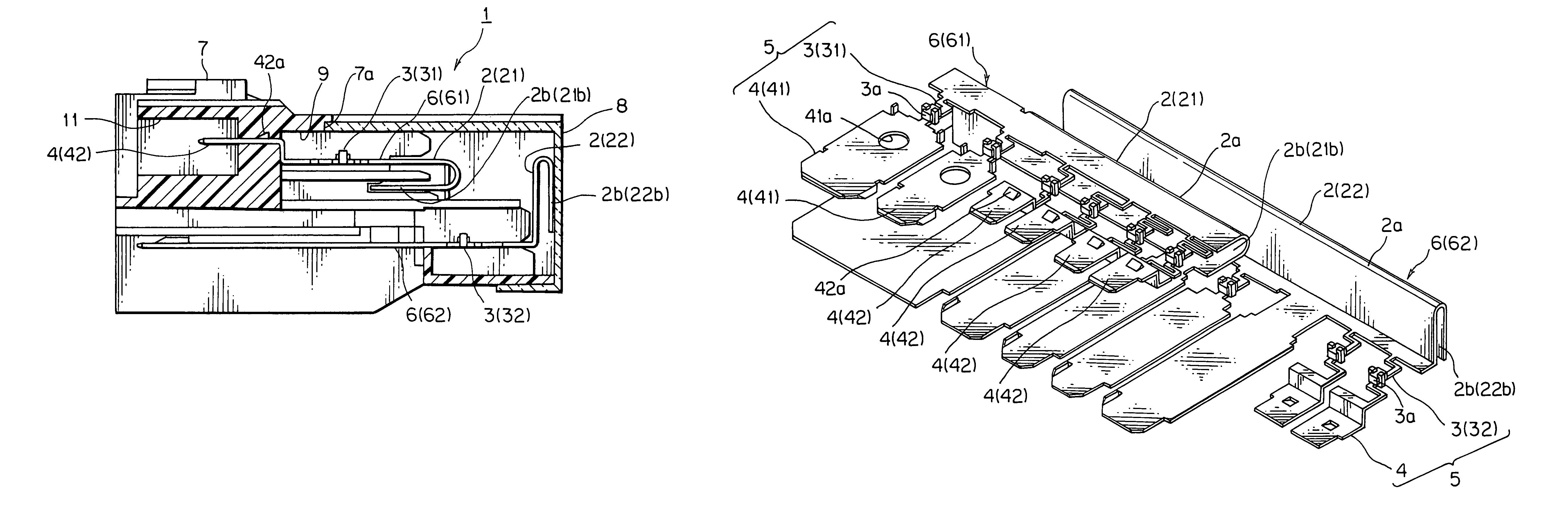
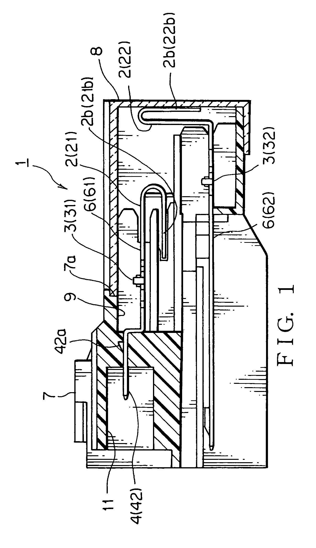
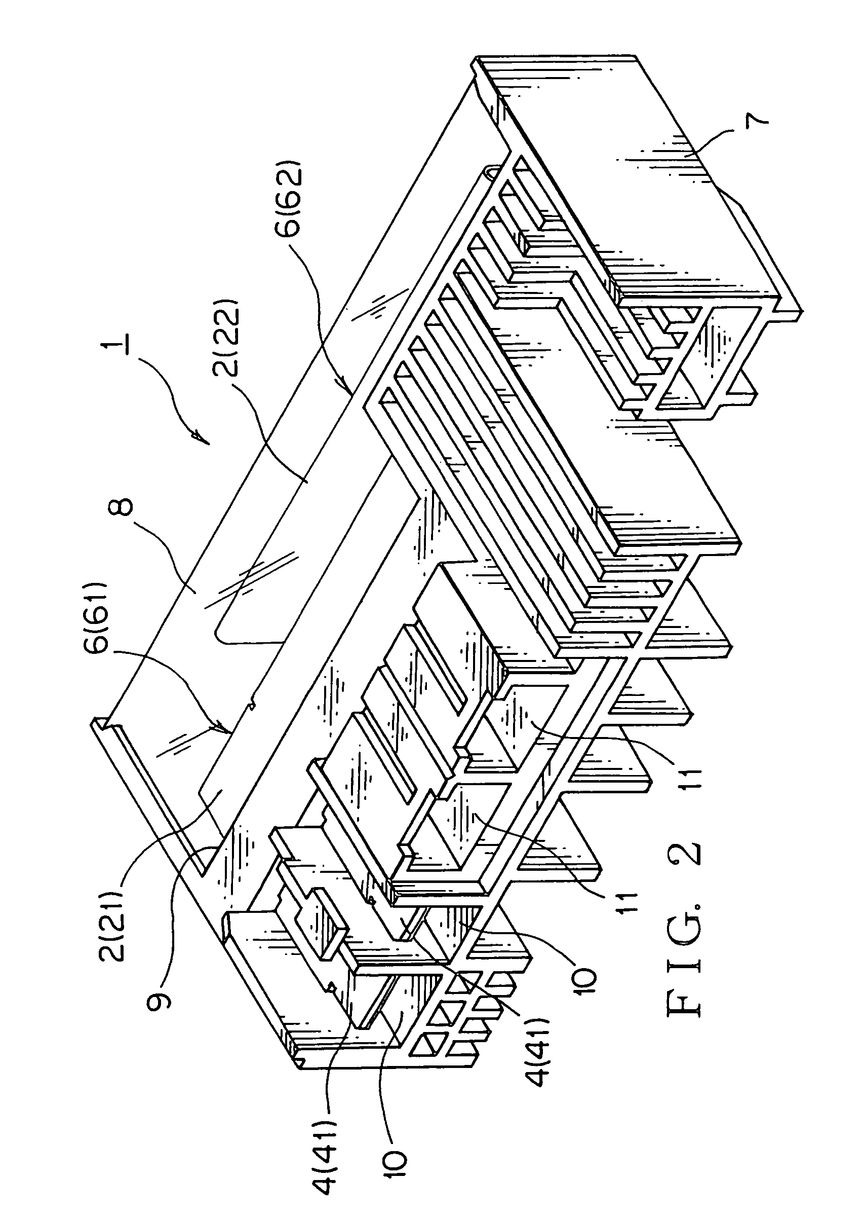
[0033]Referring to FIGS. 1 to 4, a fusible link of an embodiment according to the present invention will be discussed.

[0034]A fusible link 1 according to the present invention has a connection plate 2, a fusible portion 3 continuous with one side of the connection plate 2, and a terminal 4 continuous with the fusible portion 3. The fusible portion 3 and the terminal 4 constitute a fuse element 5. The fuse element 5 is continuous with the connection plate 2 to define a fuse circuit 6. The fuse circuit 6 is received in a housing 7.

[0035]As shown in FIG. 3, the connection plate 2 is a common terminal of the fuse circuit 6 and serves as a busbar plate used for a ground circuit.

[0036]The fusible portion 3 continuous with one side of the connection plate 2 has a crank-shape with a small width. In a middle of the crank-shaped fusible portion 3, a low fusing point metal 3a is clamped and secured thereto. When an electrical current larger than a predetermined value runs in the fusible portio...


PUM


Abstract

A plurality of fuse circuits are layered with a space therebetween in a housing. A fusible portion of one of the layered fuse circuits is offset from a fusible portion of an adjacent one of the layered fuse circuits perpendicularly to a direction in which the fuse circuits are layered. A connection plate of one of the layered fuse circuits is offset from a connection plate of an adjacent one of the layered fuse circuits perpendicularly to a direction in which the fuse circuits are layered. The connection plate has a U-shaped extended portion.

Description

BACKGROUND OF THE INVENTION[0001]1. Field of the Invention[0002]The present invention relates to a fusible link used for electrical circuits of an automotive vehicle or the like.[0003]2. Background Art[0004]An automotive vehicle is arranged with various types of electrical equipment. In electrical circuits to supply electrical power from a battery to the electrical equipment, a fusible link is mounted to serve as a fuse device to protect the circuits from an overcurrent. Such an art is disclosed, for example, in Japanese Patent Application Laid-open No. 2004-127698.[0005]The fusible link has a connection plate, a fusible portion continuous with one side of the connection plate, and a terminal continuous with the fusible portion. The fusible portion and the terminal constitute a fuse element. The fuse element is continuous with the connection plate to define a fuse circuit. The fuse circuit is received in a housing.[0006]In the housing, a plurality of the fuse circuits are layered wi...

Claims


Application Information

Patent Timeline
Patent Type & Authority Patents(United States)
IPC IPC(8): H01H85/143H01H85/165
CPCH01H85/2045H01H85/47H01H2085/208H01H2085/0555
Inventor ONODA, SHINYAKUDO, TOSHIHARUNAKAHAMA, YOSHIHIKOKAWAI, TAKANORI
Owner YAZAKI CORP
Why Eureka
Try Eureka