Audio encoder and audio decoder

a technology of encoder and encoder, applied in the field of encoder, can solve the problems of difficult to skip difficult to obtain the size of difficult to separate the first coded signal and the second coded signal in the mpeg-2 audio standard, so as to reduce the power to drive the audio decoder and the effect of less number of operations

Active Publication Date: 2009-11-03
PANASONIC CORP
View PDF8 Cites 50 Cited by
  • Summary
  • Abstract
  • Description
  • Claims
  • Application Information

AI Technical Summary

Benefits of technology

[0029]According to the present invention, it becomes possible to generate a coded signal that makes it easy to find a code size of the second coded signal for an audio decoder. Here the second coded signal is obtained by coding necessary information to restore the downmixed signal to a multi-channel signal. Hence a reproducing device for reproducing only a downmixed signal is able to decode and reproduce only the downmixed signal easily.
[0038]Furthermore, according to the present invention, after filter processing based on the head-related transfer function in a frequency domain is executed, and then a frequency domain signal for two channels is generated. The frequency domain signal can be converted into a time domain signal, and in the case where the audio compression technologies, which are major in recent years such as the AAC standard (ISO / IEC13818-7) and the AAC-SBR standard (ISO / IEC 14496-3), are combined, the processing can be executed with less number of operations. This is because these standards are the methods of compression coding for the signal in a frequency domain.

Problems solved by technology

However there has been a problem that separating the first coded signal and the second coded signal is not easy in the MPEG-2 audio standard.
However, is not possible to obtain the size of the second coded signal 902 easily due to the following reason, so that it is not easy to skip the second coded signal 902.
As a result, there exists a problem that a large volume of operation resources needs to be spent undesirably.
Additionally, the following problem is also apparent in the conventional technique.
As a result there exists a problem that a large volume of operation resources needs to be spent undesirably.

Method used


Image

  • Audio encoder and audio decoder
  • Audio encoder and audio decoder
  • Audio encoder and audio decoder

Examples


first embodiment

THE FIRST EMBODIMENT

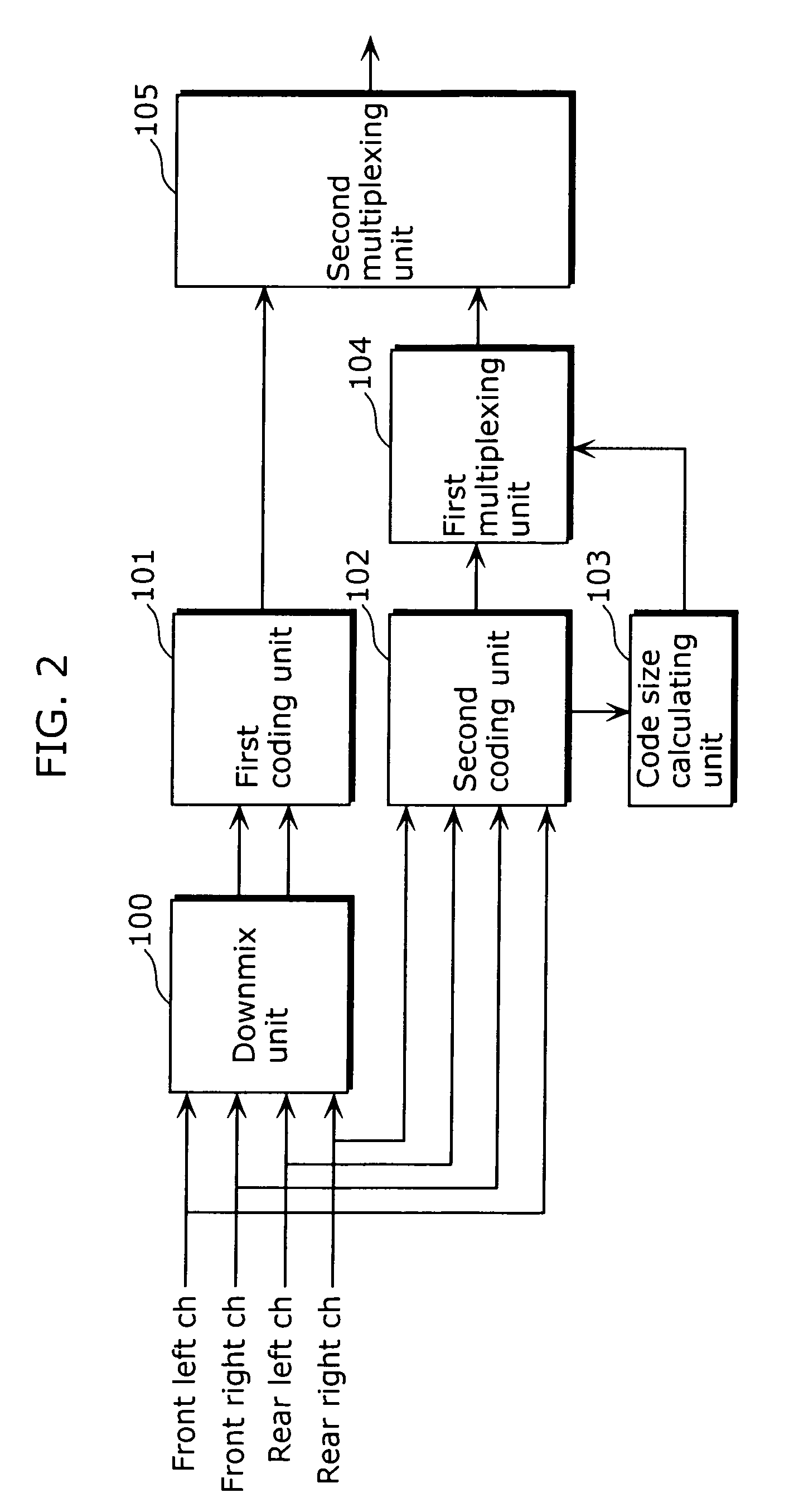
[0070]Here an audio encoder of the first embodiment of the present invention will be described referring to drawings. FIG. 2 is a diagram showing a configuration of the audio encoder of the first embodiment. The audio encoder of the first embodiment shown in FIG. 2 is an audio encoder which describes a signal representing a code size of the second coded signal at the head of the second coded signal for each frame, and one frame includes variable-length of the first coded signal and the second coded signal respectively. The audio encoder includes a downmix unit 100, a first coding unit 101, a second coding unit 102, a code size calculating unit 103, a first multiplexing unit 104 and a second multiplexing unit 105. The first coded signal is obtained by coding a stereo signal of two channels obtained by downmixing a multi-channel signal. The second coded signal is obtained by coding information to restore the original multi-channel signal from the first coded signal...

second embodiment

THE SECOND EMBODIMENT

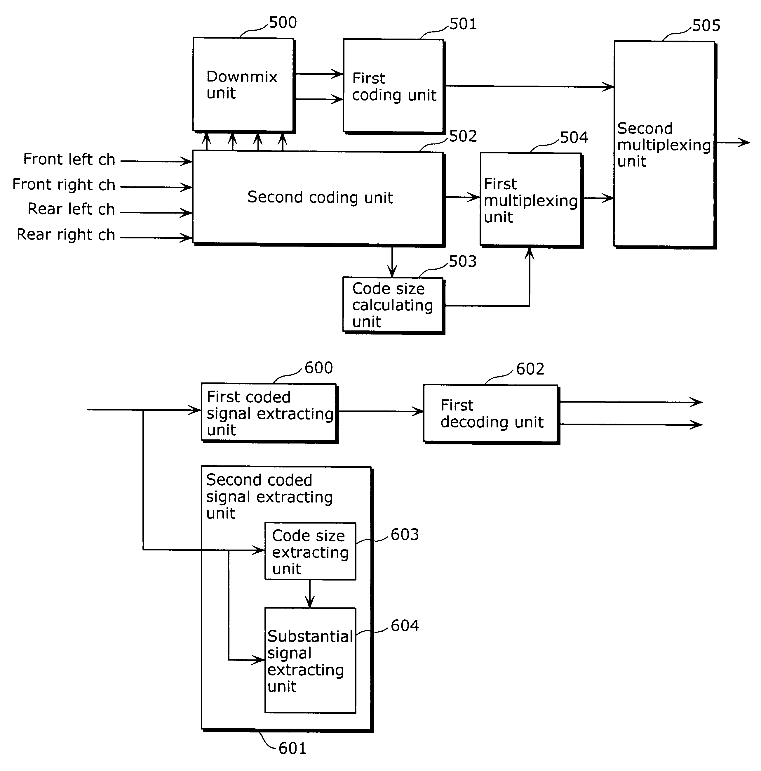
[0083]Here an audio encoder of the second embodiment of the present invention will be described referring to drawings. FIG. 8 is a diagram showing a configuration of an audio encoder of the second embodiment. The audio encoder of FIG. 8 is an audio encoder for transforming a 4-channel signal on a time domain inputted to a signal in a frequency domain, and subsequently downmixing the signal. The audio encoder includes a downmix unit 500, a first coding unit 501, a second coding unit 502, a code size calculating unit 503, a first multiplexing unit 504 and a second multiplexing unit 505. Here the second coding unit 502, the code size calculating unit 503, the first multiplexing unit 504 and the second multiplexing unit 505 are the same units as shown in the first embodiment. The second embodiment is different from the first embodiment in that: the downmix unit 500 is configured so that it receives a frequency domain signal of each input channel generated in the pro...

third embodiment

THE THIRD EMBODIMENT

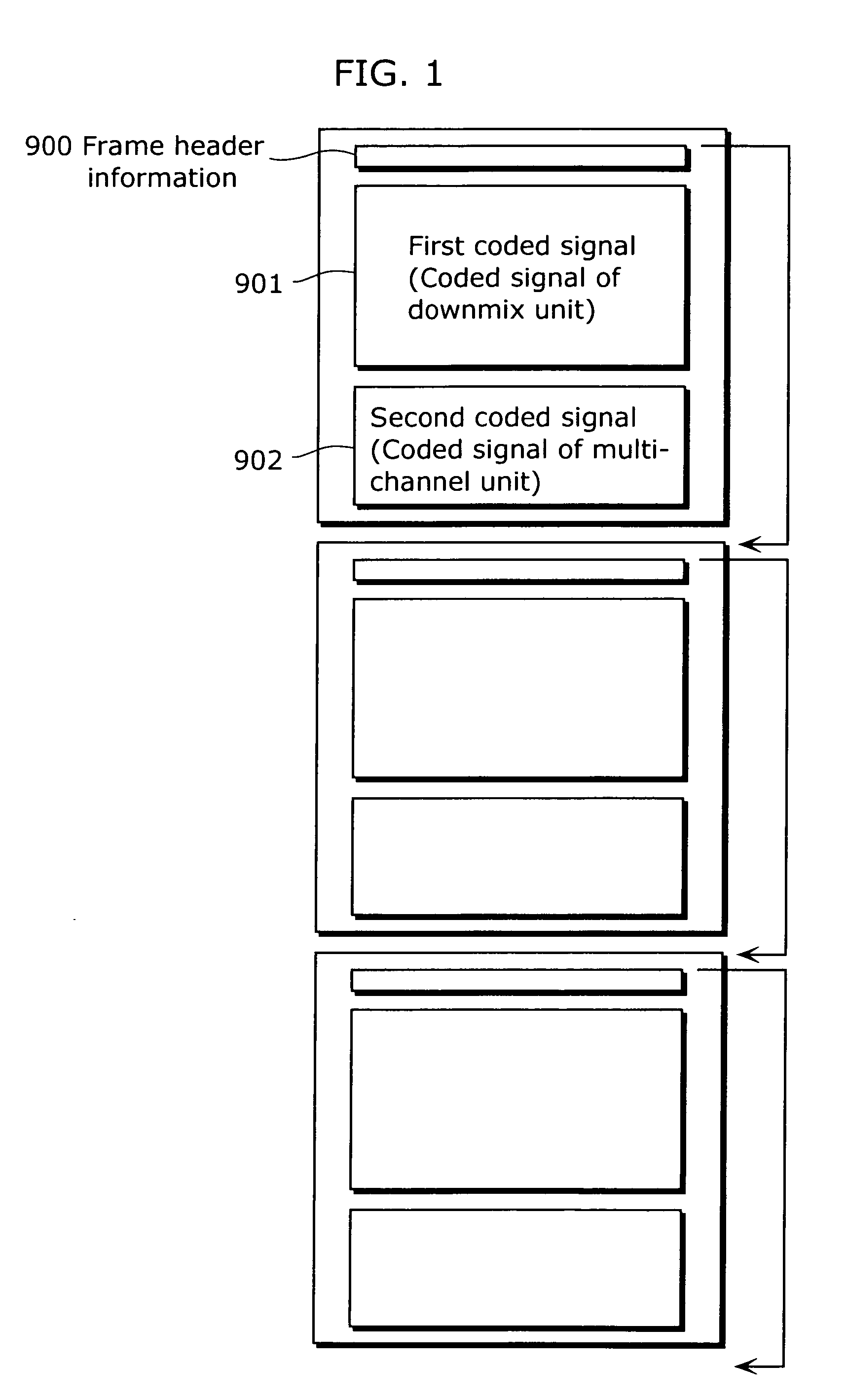
[0092]Here an audio decoder of the third embodiment of the present invention will be described referring to drawings. The audio decoder is an audio decoder for decoding the coded signal generated by coding a signal in the first embodiment or the second embodiment. In fact, the audio decoder is a decoder for decoding a coded signal which is multiplexed a first coded signal and a second coded signal. Here the first coded signal is generated by downmixing a multi-channel signal of M channels (M>2) to a stereo signal and then coding the stereo signal, and the second coded signal is generated by coding the information to restore the downmixed signal to a multi-channel signal. Here a value indicating a code size of the second coded signal is multiplexed in the second coded signal.

[0093]FIG. 9 is a diagram showing a configuration of an audio decoder of the third embodiment. In FIG. 9, the audio decoder includes a first coded signal extracting unit 600, a second coded si...


PUM


Abstract

An audio encoder, generating a stereo signal based on a multi-channel signal, includes a downmix unit for downmixing a multi-channel signal exceeding two channels to a two-channel stereo signal, a first coding unit for generating a first coded signal by coding the downmixed stereo signal, a second coding unit for generating a second coded signal by coding information to restore the downmixed stereo signal to a multi-channel signal, a code size calculating unit for calculating a code size of the second coded signal, and a first multiplexing unit for multiplexing the calculated code size in either the first coded signal or the second coded signal. Accordingly a decoder is able to easily extract a coded signal of the multi-channel signal based on the code size, and the decoder reproducing only the downmixed signal can be configured inexpensively.

Description

BACKGROUND OF THE INVENTION[0001]1 Technical Field[0002]The present invention relates to an audio encoder which codes a multi-channel signal, and particularly relates to an audio encoder which generates a coded signal that allows the multi-channel signal to be reproduced by an inexpensive decoder.[0003]The present invention also relates to an audio decoder which decodes the coded signal encoded by the aforementioned audio encoder, and particularly relates to an audio decoder which reproduces the multi-channel signal by two channels.[0004]2 Background Art[0005]Conventionally researches and developments related to an audio encoder, which generates a coded signal that allows the multi-channel signal to be reproduced by an inexpensive reproducing device especially by a two-channel reproducing device, have been carried out. For example the MPEG-2 audio standard (ISO13818-3) discloses a technique that a signal downmixed from a multi-channel signal to a two-channel signal and a signal to r...

Claims


Application Information

Patent Timeline
Patent Type & Authority Patents(United States)
IPC IPC(8): H04R5/00G10L19/008
CPCG10L19/008
Inventor MIYASAKA, SHUJITAKAGI, YOSHIAKIABE, KAZUTAKA
Owner PANASONIC CORP
Why Eureka
Try Eureka