Endoscope

a technology of endoscope and endoscope, which is applied in the field of endoscope, can solve the problems of uncontrollable movement of optical devices, and achieve the effect of preventing twisting of connection lines and good protection of optical devices

Active Publication Date: 2009-11-10
AESCULAP AG
View PDF44 Cites 55 Cited by
  • Summary
  • Abstract
  • Description
  • Claims
  • Application Information

AI Technical Summary

Benefits of technology

[0007]This configuration makes it possible for the optical device to be held in precisely defined positions at least in the longitudinal direction of the shaft. An undesired relative movement between the shaft and the optical device is thereby avoided. By selecting two positions, for example, a diagnosis position and a work position, the optical device can be employed in the desired manner. Thus, for example, in the diagnosis position, it can protrude far beyond the distal end of the endoscope without the distal end of the endoscope or tools arranged thereon impeding a view of the operating site. By transferring the optical device from the diagnosis position to the second position serving, for example, as work position, an optical monitoring of employment of tools arranged on the shaft is rendered possible in a defined manner. In the second position, a free end of the optical device could, however, also be retracted into the shaft to such an extent that the optical device is protected. Owing to the possibility of axially fixing the optical device in two positions relative to the shaft, considerably easier and safer handling of the endoscope is possible.
[0030]For use of the endoscope in the field of high-frequency surgery, it is advantageous for an HF connecting device to be provided for connecting the endoscope to a high-frequency generator and for this HF connecting device to be arranged so as to be rotatable relative to the optical device. Connection lines can thus also be arranged in any desired orientation, and twisting of the connection lines is thereby prevented.

Problems solved by technology

It has proven to be disadvantageous that the optical device can be moved in an uncontrolled manner.

Method used


Image

  • Endoscope
  • Endoscope
  • Endoscope

Examples


Embodiment Construction

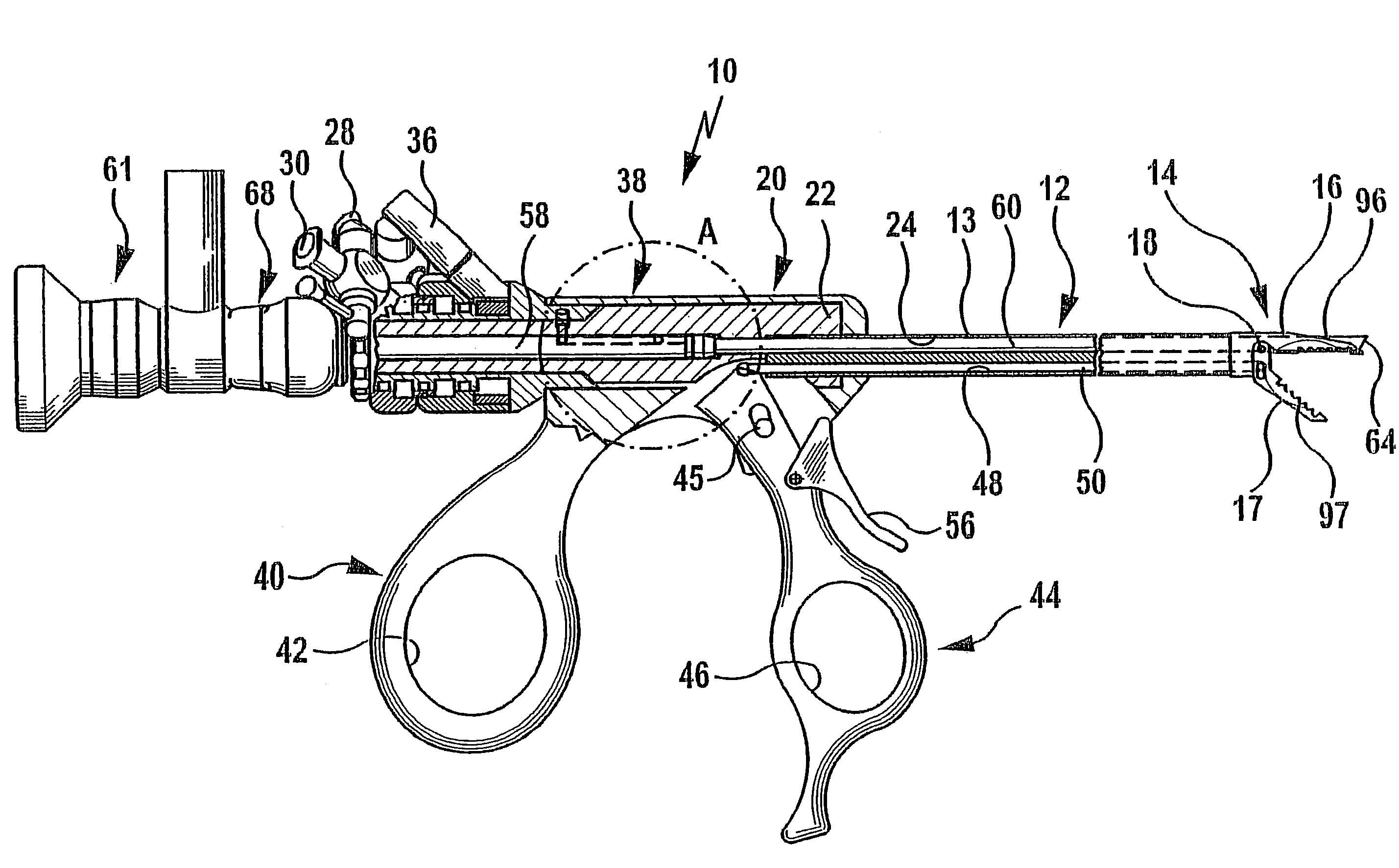
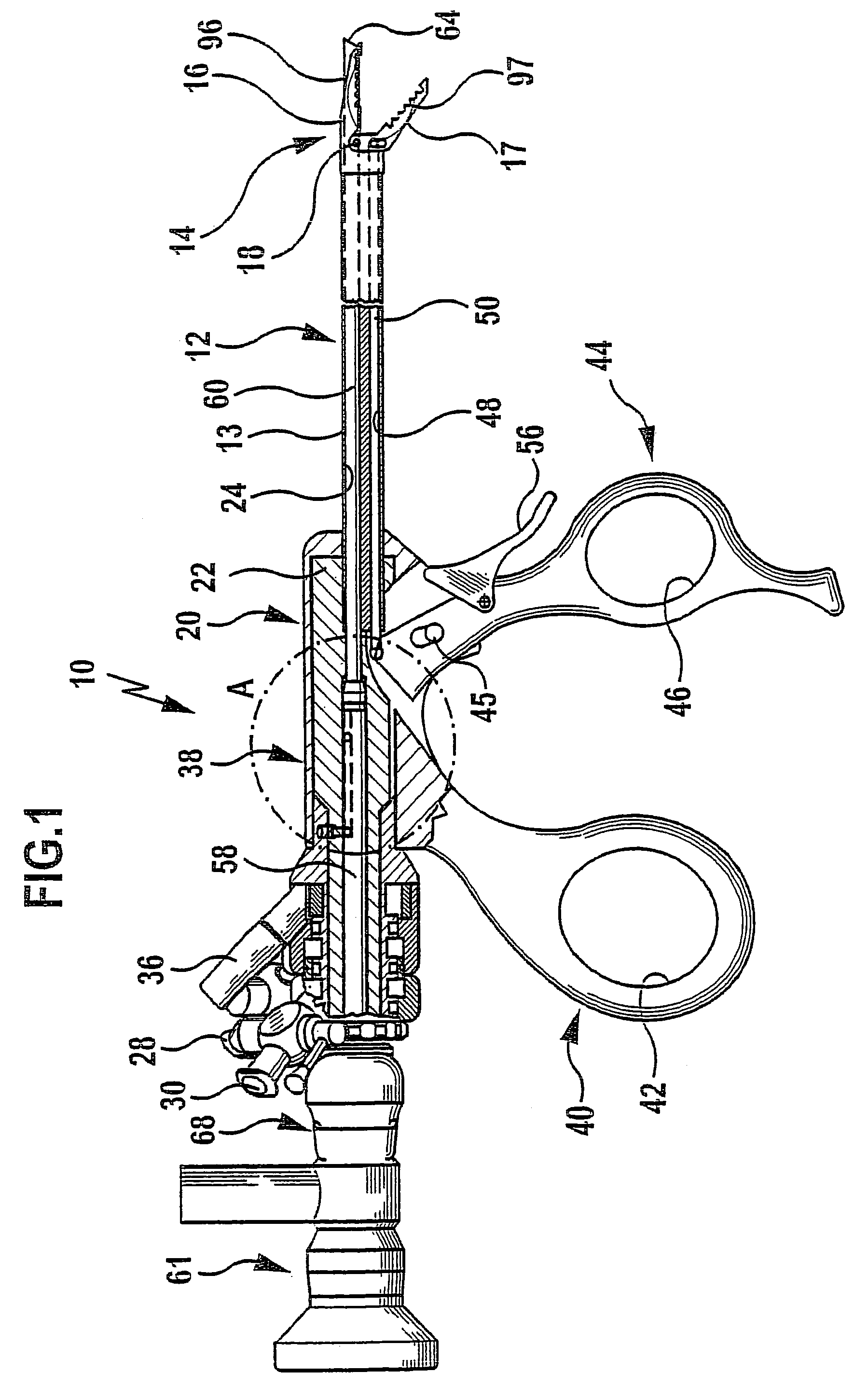
[0039]FIG. 1 shows an endoscope generally designated by reference numeral 10 with a shaft 12 for introduction into the interior of the body of a human being through an opening of the body. A surgical tool in the form of a fixation forceps 14 is arranged at the distal end of the shaft 12 for rotation about the longitudinal axis of the shaft 12 relative thereto. The fixation forceps comprises a stationary jaw part 16 and a jaw part 17 which is mounted for pivotal movement about a pivot axis 18 extending transversely to the longitudinal axis of the shaft 12.

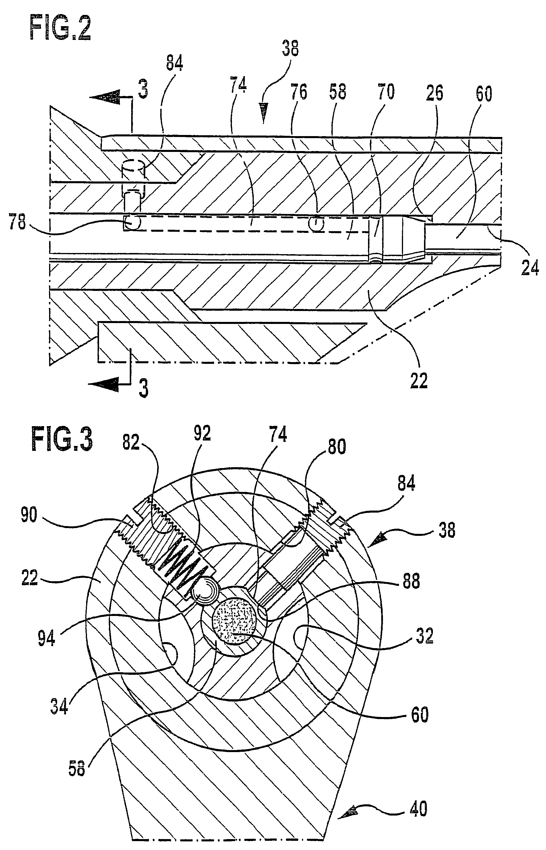
[0040]Adjoining a proximal end of the shaft 12 is a handling portion 20 of the endoscope 10, which comprises a main body 22 rigidly connected to an outer shaft sleeve 13 of the shaft 12. Extending through the shaft 12 and the main body 22 is an optical channel 24 which widens in the form of a step in the area of the main body 22 in the direction towards its proximal end, thereby forming a ring-shaped stop 26. Provided in the proxima...


PUM


Abstract

In an endoscope having a proximal end area, a distal end area introducible into the body of a human being, a shaft extending in a longitudinal direction, and an optical device extending through the shaft in the longitudinal direction thereof and movable relative to the shaft, to enable particularly easy and safe handling of the optical device it is proposed that the optical device be fixable in axial direction relative to the shaft in a first position and in at least a second position differing from the first position.

Description

[0001]This application is a continuation of international application number PCT / EP03 / 12634 filed on Nov. 12, 2003.[0002]The present disclosure relates to the subject matter disclosed in international application PCT / EP03 / 12634 of Nov. 12, 2003, which is incorporated herein by reference in its entirety and for all purposes.BACKGROUND OF THE INVENTION[0003]The invention relates to an endoscope having a proximal end area, a distal end area introducible into the body of a human being, a shaft extending in a longitudinal direction, and an optical device extending through the shaft in the longitudinal direction thereof and movable relative to the shaft.[0004]Endoscopes of the kind described hereinabove are used for various purposes when performing minor surgery on the human body. An operating surgeon can view the operating site with the aid of the optical device extending through the shaft. With conventional endoscopes, the optical device is introducible from the proximal end into the sh...

Claims


Application Information

Patent Timeline
Patent Type & Authority Patents(United States)
IPC IPC(8): A61B1/00A61B1/313A61B17/28A61B18/14
CPCA61B1/00165A61B1/313A61B19/5212A61B18/14A61B17/29A61B90/361
Inventor ROTHWEILER, CHRISTOPHGROSSMANN, ANDREAS
Owner AESCULAP AG
Why Eureka
Try Eureka