Switchgear control apparatus

a control apparatus and switchgear technology, applied in the direction of electric switches, emergency protective arrangements for automatic disconnection, electric devices, etc., can solve the problem that the conventional control technique is not useful from a practical point of view, and achieve the effect of effectively suppressing a surge voltage occurring and being practical

Active Publication Date: 2009-11-10
MITSUBISHI ELECTRIC CORP
View PDF8 Cites 11 Cited by
  • Summary
  • Abstract
  • Description
  • Claims
  • Application Information

AI Technical Summary

Benefits of technology

[0006]The present invention is intended to provide a solution to the aforementioned problem of the prior art. More particularly, it is an object of the invention to provide a highly practical switchgear control apparatus having a capability to effectively suppress a surge voltage occurring when an unloaded power line once disconnected is reconnected without the need for a special type of voltage sensor system for measuring a residual DC voltage on the unloaded power line.
[0008]The switchgear control apparatus of the invention is configured to detect the AC voltage on the power source side of the circuit breaker, the main circuit current flowing through the circuit breaker and the contact opening time of the main contact of the circuit breaker, and to determine the reclosing time at which the main contact of the circuit breaker should be reclosed based on the detected AC voltage, main circuit current and contact opening time. Therefore, the present invention provides a highly practical switchgear control apparatus which can suppress a surge voltage occurring when an unloaded power line once disconnected is reconnected without the need for a special type of voltage sensor system capable of detecting a DC voltage component.

Problems solved by technology

However, such a special type of voltage sensor system is not provided in a generally used power system so that the conventional control technique is not useful enough from a practical point of view.

Method used


Image

  • Switchgear control apparatus
  • Switchgear control apparatus
  • Switchgear control apparatus

Examples


first embodiment

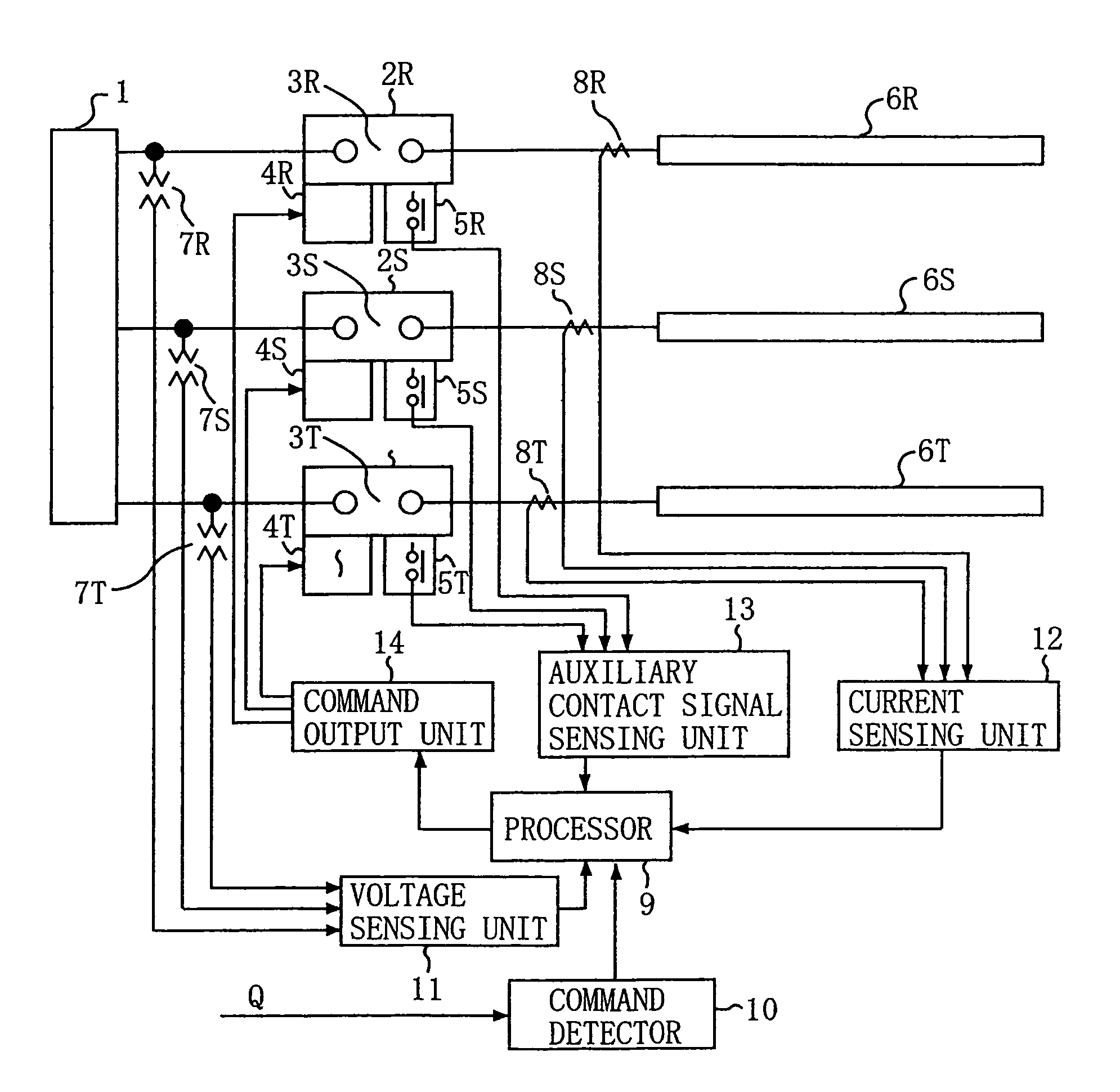
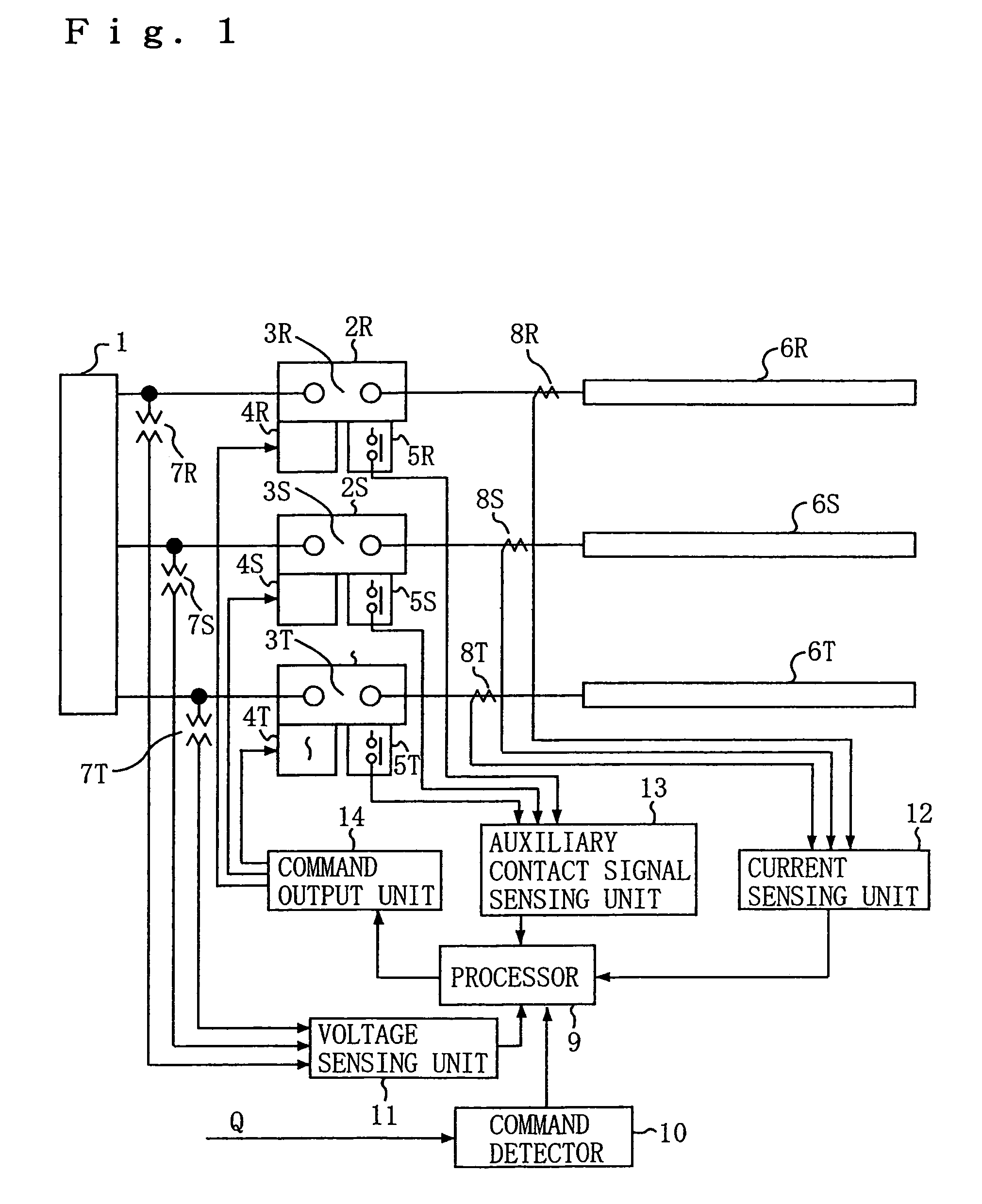
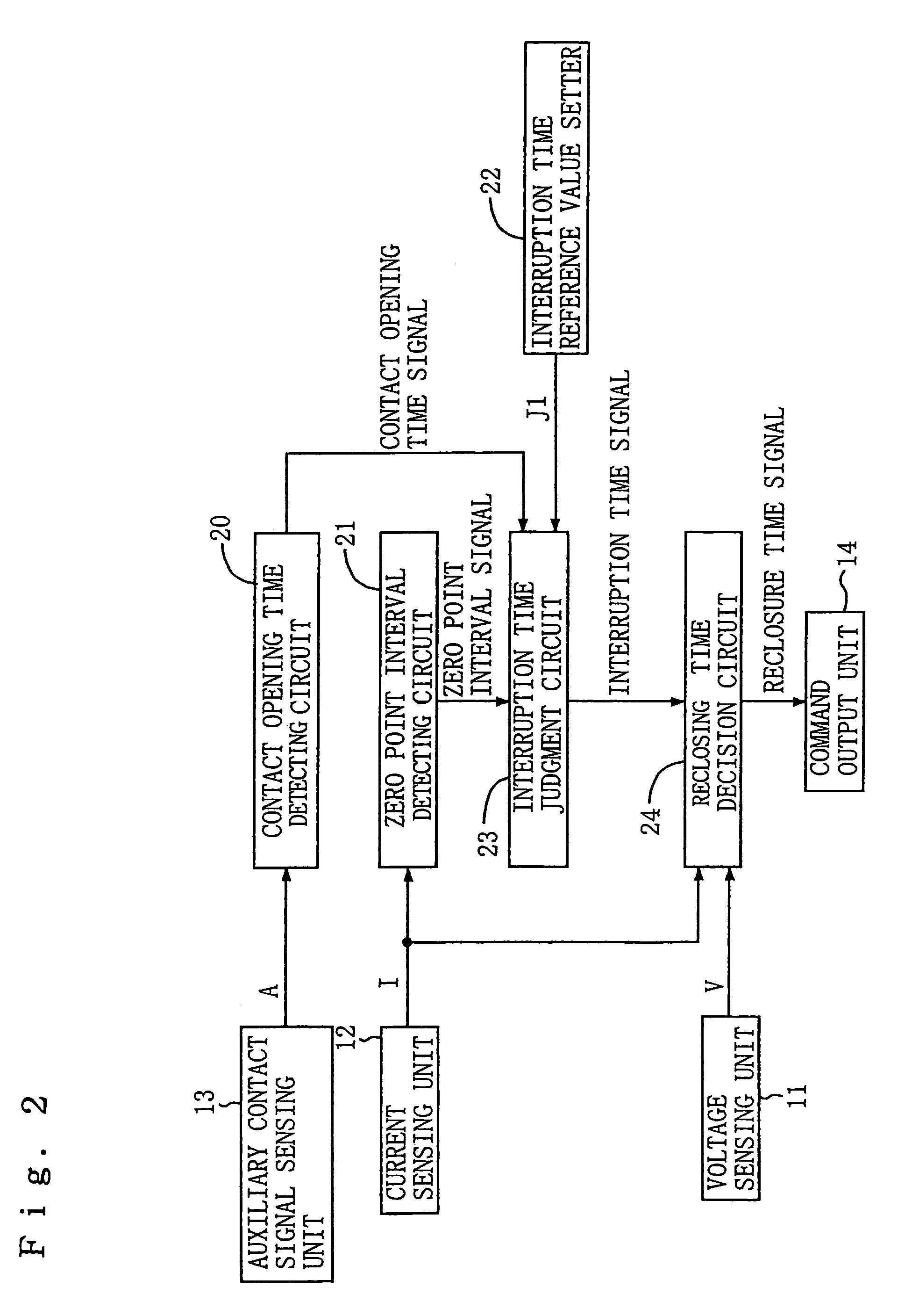
[0013]FIG. 1 is a diagram showing the configuration of a power system including a switchgear control apparatus according to a first embodiment of the invention, and FIG. 2 is a block diagram showing the internal configuration of a processor 9 of the switchgear control apparatus constituting a principal part thereof.

[0014]Referring to FIG. 1, a three-phase power source 1 is connected to transmission lines 6R, 6S, 6T via respective circuit breakers 2R, 2S, 2T which may be opened and closed for disconnecting and reconnecting the transmission lines 6R, 6S, 6T under no-load conditions, respectively. The circuit breakers 2R, 2S, 2T of individual phases (indicated by R, S and T) are provided with main contact s 3R, 3S, 3T for interrupting and flowing main circuit currents through the circuit breakers 2R, 2S, 2T, auxiliary contacts 5R, 5S, 5T which make and break in a manner mechanically interlocked with the main contact s 3R, 3S, 3T, and operating mechanisms 4R, 4S, 4T for causing the main...

second embodiment

[0039]The interruption time judgment circuit 23 of the foregoing first embodiment determines the interruption time from the detected current signal I based on whether the difference between the successively detected time interval detected by the zero point interval detecting circuit 21 and half the period of the power frequency exceeds the specific interruption time reference value J1. This arrangement of the first embodiment is modified in a switchgear control apparatus according to a second embodiment of the invention as described hereinbelow. The following discussion focuses on how the switchgear control apparatus of the second embodiment detects a change in zero point intervals as the switchgear control apparatus works otherwise the same way as that of the first embodiment.

[0040]The interruption time judgment circuit 23 of the switchgear control apparatus of the second embodiment evaluates the amount of a change in zero point intervals successively detected by the zero point int...


PUM


Abstract

A switchgear control apparatus includes a zero point interval detecting circuit, an interruption time judgment circuit and a reclosing time decision circuit. The zero point interval detecting circuit detects time intervals between successive zero points of a main circuit current. The interruption time judgment circuit judges that interruption time of the main circuit current is time of a zero point immediately preceding a zero point at which a difference between the time interval between two successive zero points and half the period of a commercial AC voltage exceeds a specific value. Upon detecting the gradient of the main circuit current at the interruption time, the reclosing time decision circuit sets reclosing time at a point in phase where the AC voltage has a maximum negative value if the gradient is positive, and at a point in phase where the AC voltage has a maximum positive value if the gradient is negative.

Description

BACKGROUND OF THE INVENTION[0001]1. Field of the Invention[0002]The present invention relates to a switchgear control apparatus for controlling opening / closing operation of each circuit breaker of a switchgear which disconnects and reconnects a power transmission line and, more particularly, the invention is concerned with a technique for suppressing a surge voltage which occurs when a power line is reconnected under no-load conditions.[0003]2. Description of the Background Art[0004]Conventionally, a controlled switching technique is used for suppressing a surge voltage which occurs when a power transmission line once disconnected is reconnected under no-load conditions. This control technique involves detecting a voltage across opposite terminals of a switchgear and closing the switchgear at a point in time when the opposite switchgear terminals have a common polarity as described in Japanese Unexamined Patent Publication Nos. 1980-151724 and 1980-151725, for instance.[0005]In the ...

Claims


Application Information

Patent Timeline
Patent Type & Authority Patents(United States)
IPC IPC(8): H02H3/12
CPCH01H9/56H01H9/563
Inventor KOYAMA, HARUHIKOMORI, TOMOHITOKAMEI, KENJIKINOSHITA, SADAYUKI
Owner MITSUBISHI ELECTRIC CORP
Why Eureka
Try Eureka