
Frequency offset estimating method and receiver employing the same

a frequency offset and receiver technology, applied in the field of frequency offset estimation and receiver, can solve the problems of large number of memory and a lot of hardware operation quantity, complicated operation process, and interruption of normal signal restoration

Inactive Publication Date: 2009-11-10
ELECTRONICS & TELECOMM RES INST
View PDF0 Cites 55 Cited by
  • Summary
  • Abstract
  • Description
  • Claims
  • Application Information

AI Technical Summary

Problems solved by technology

This interrupts normal restoration of the signal.
Therefore, a large number of memories and a lot of hardware operation quantity are required to improve performance.
However, the above-mentioned technique requires a complicated operation process in a maximum value search procedure.

Method used


Image

  • Frequency offset estimating method and receiver employing the same
  • Frequency offset estimating method and receiver employing the same
  • Frequency offset estimating method and receiver employing the same

Examples


Embodiment Construction

[0022]Other objects and advantages of the present invention will become apparent from the following description of the embodiments with reference to the accompanying drawings. Therefore, those skilled in the art that the present invention is included can embody the technological concept and scope of the invention easily. In addition, if it is considered that detailed description on the prior art may blur the points of the present invention, the detailed description will not be provided herein. The preferred embodiments of the present invention will be described in detail hereinafter with reference to the attached drawings.

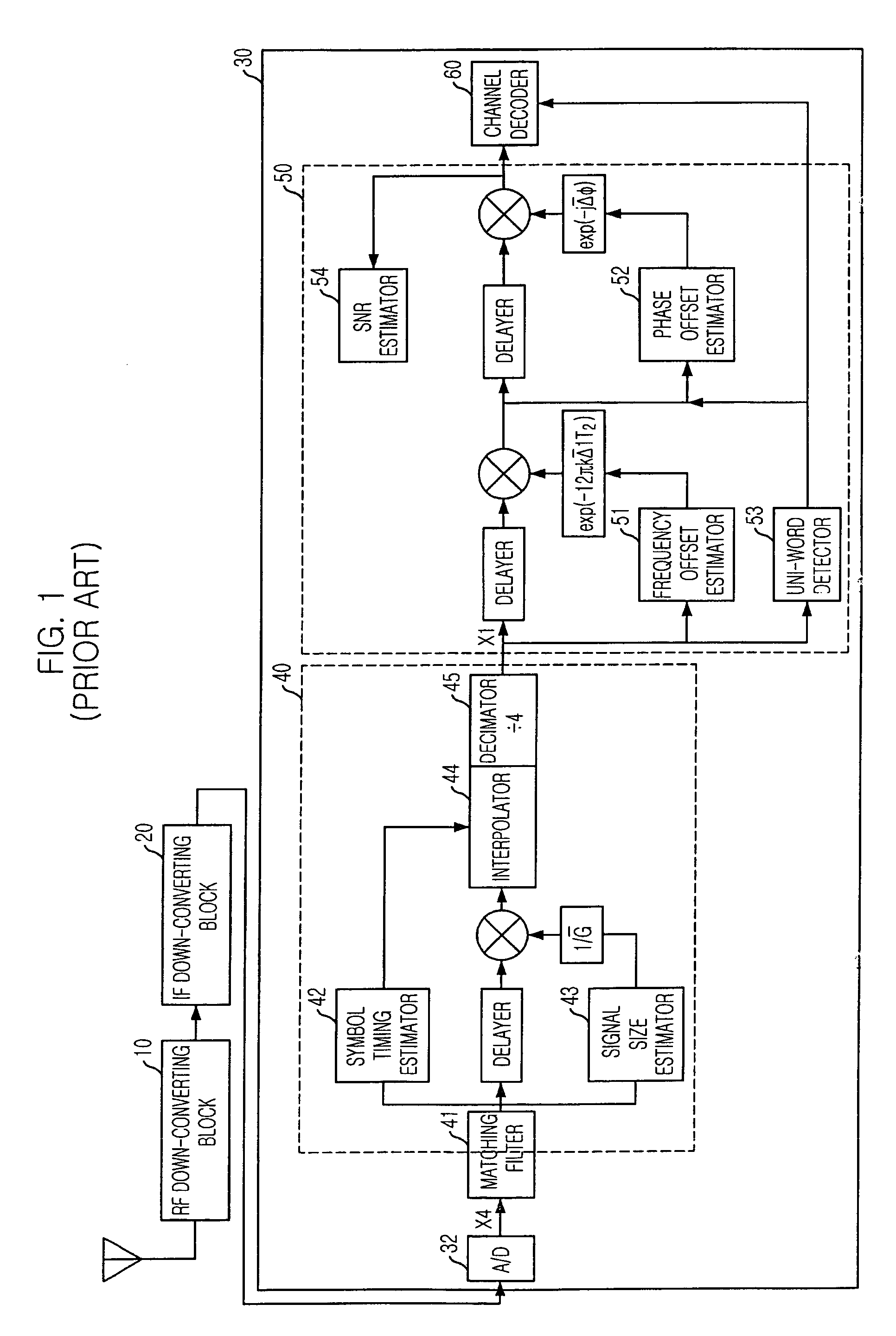
[0023]FIG. 1 is a block diagram showing a general receiver, to which the present invention is applied.

[0024]A Radio Frequency (RF) reception signal is inputted into a demodulating block30 after transformed into a baseband signal through an RF down-converting block 10 and an Intermediate Frequency (IF) down-converting block 20. A carrier wave frequency offset and a ...


PUM


Abstract

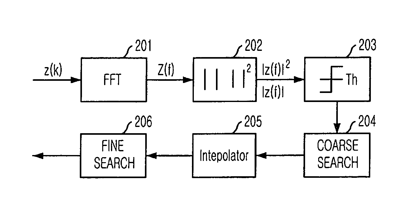
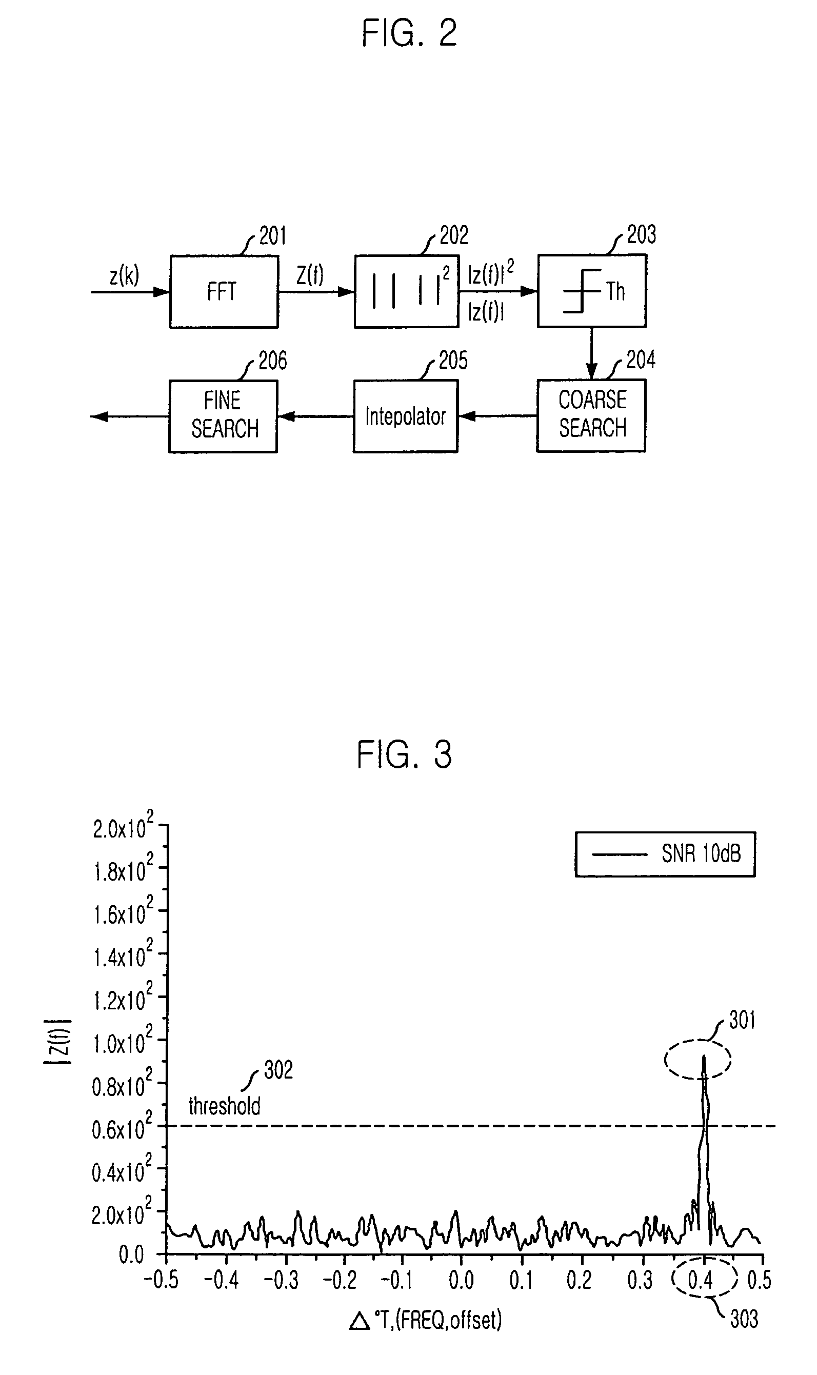
Provided is a method for estimating carrier wave or doppler frequency offset based on an approximated quadratic non-linear function in fine search, and a receiver employing the method. The method for estimating frequency offset includes the steps of: a) extracting more than three discrete samples in an order where the discrete samples are close to a maximum value of a power spectrum density function; b) inducing a quadratic non-linear function by using the extracted discrete samples; and c) estimating the frequency offset from a maximum point of the quadratic non-linear function. The technology of the present research makes it possible to exactly estimate frequency offset without increasing hardware complexity in estimation of carrier wave or doppler frequency offset.

Description

FIELD OF THE INVENTION[0001]The present invention relates to a method for estimating frequency offset and a receiver employing the same; and, more particularly, to a method for estimating carrier wave or doppler frequency offset by using an approximated quadratic non-linear function in fine search and a receiver using the method.DESCRIPTION OF RELATED ART[0002]Generally, a receiver of a communication system down-converts a received Radio Frequency (RF) signal into a baseband signal through an RF module and an Intermediate Frequency (IF) module and restores an original signal in a demodulator.[0003]Herein, a signal with carrier wave frequency offset generated due to incompleteness of an analog local oscillator used in the RF module and the IF module is inputted in the demodulator. Also, a signal with the doppler frequency offset, which is generated from motion of the receiver, is inputted in the demodulator. This interrupts normal restoration of the signal.[0004]Therefore, the signal...

Claims


Application Information

Patent Timeline
Patent Type & Authority Patents(United States)
IPC IPC(8): H04L27/14
CPCH04L27/0014H04L2027/0065H04L2027/0046H04L2027/003
Inventor KIM, PAN-SOOSONG, YUN-JEOUGKIM, BYOUNG-HAKOH, DEOCK-GILLEE, HO-JIN
Owner ELECTRONICS & TELECOMM RES INST
Learn More