
Apparatus and method for supporting transmission of sounding reference signals from multiple antennas

Active Publication Date: 2010-04-01
SAMSUNG ELECTRONICS CO LTD
View PDF10 Cites 280 Cited by
  • Summary
  • Abstract
  • Description
  • Claims
  • Application Information

AI Technical Summary

Benefits of technology

[0046]The present invention has been made to address at least the above problems and / or disadvantages and to provide at least the advantages described below. Accordingly, an aspect of the present invention provides methods and apparatus for dynamic activation of Sounding Reference Signal (SRS) transmissions from User Equipments (UEs) in the UpLink (UL) of a communication system, for dynamic configuration of the SRS transmission parameters, for activation and configuration of SRS transmissions in component carriers not having configured SRS transmission from a reference UE, and for configuration of SRS transmission parameters from multiple UE transmitter antennas.

Problems solved by technology

For example, a short SRS transmission period may only result in increased UL overhead if the channel remains highly correlated between two successive SRS transmissions.
Conversely, a long SRS transmission period may not provide the Node B with the proper UL CQI in sub-frames between two SRS transmissions for which the channel may become highly uncorrelated.
This reduces the SRS multiplexing capacity and results in increased UL overhead.
Considering that a UE may have as many as four or even eight transmitter antennas, the UL overhead required to support SRS transmissions may become too large and offset a significant part of the SU-MIMO spectral efficiency gains.
Configuring the SRS transmission parameters to remain constant over a long time period may often result in underutilization of the respective overhead.
When the UE has no data to transmit, and hence is not scheduled by the Node B, relatively frequent SRS transmissions are wasteful.
However, this is not possible with a semi-static configuration of the SRS transmission parameters through higher layer (MAC or RRC) signaling without incurring prohibitive SRS overhead.

Method used


Image

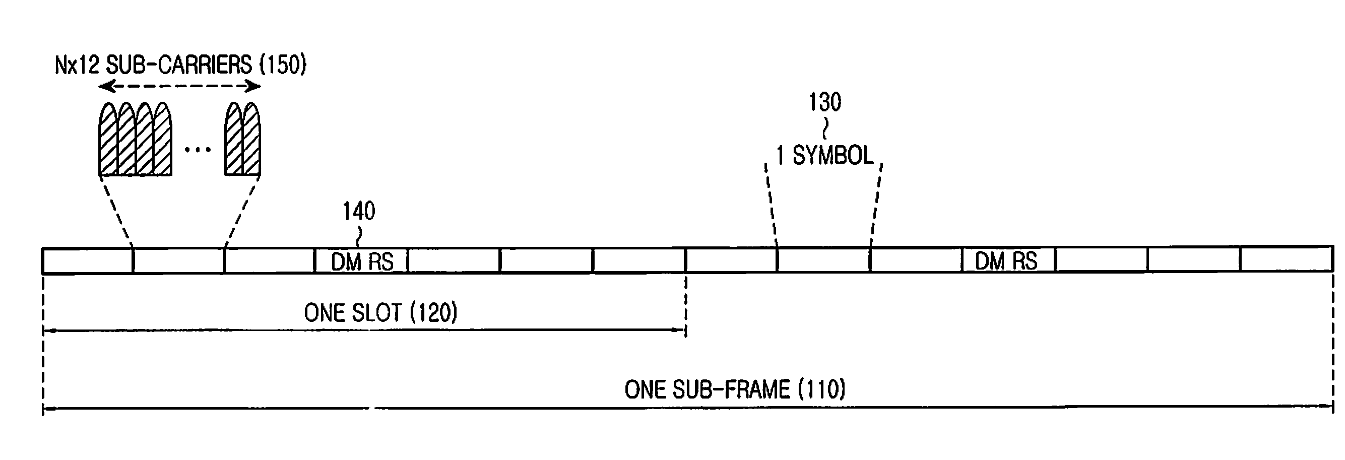
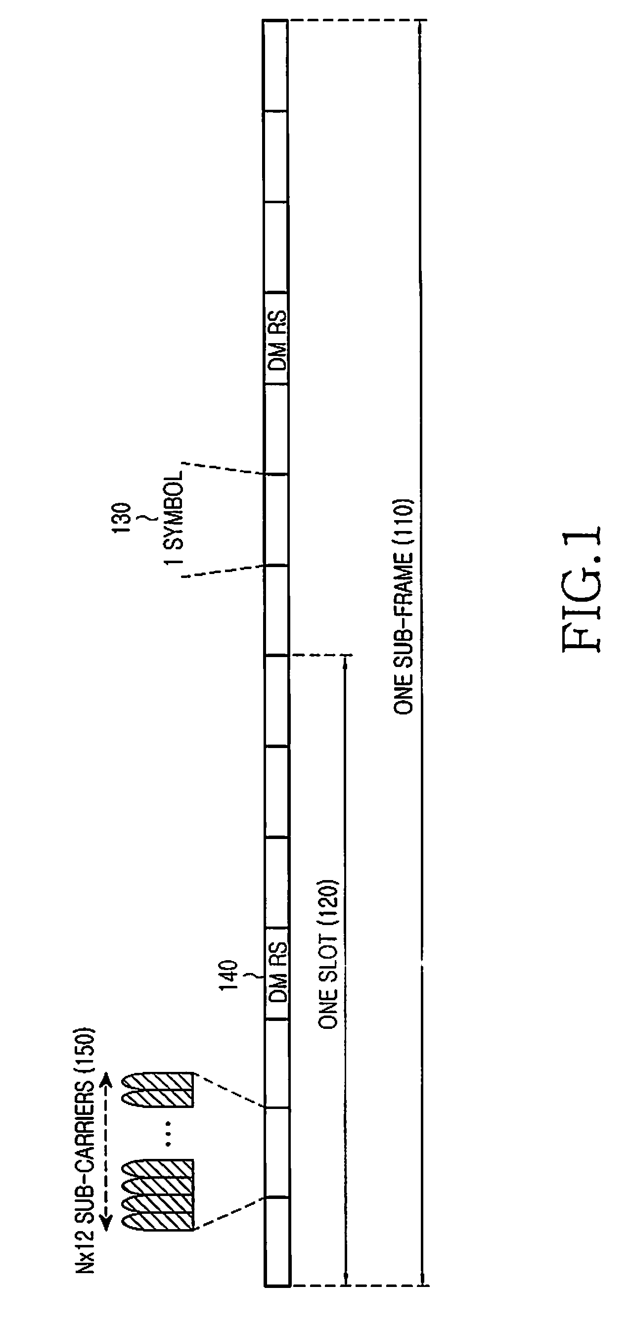
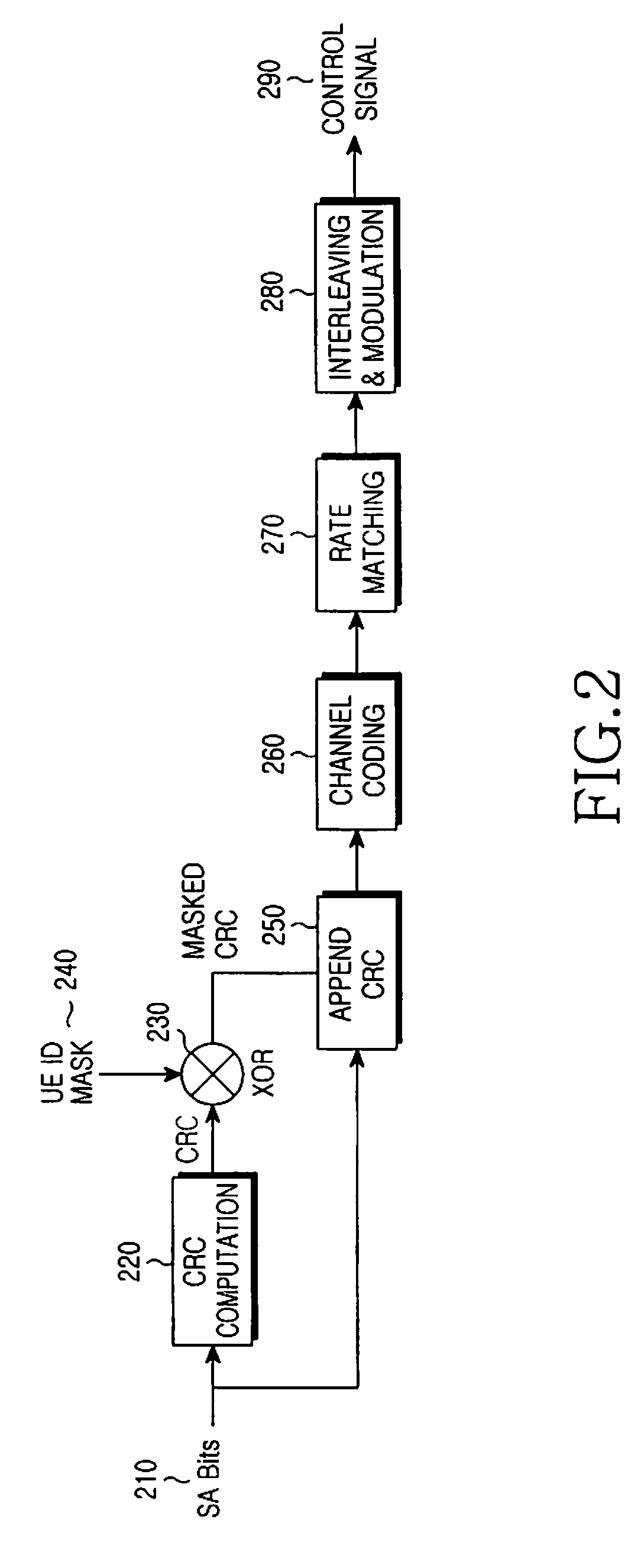
  • Apparatus and method for supporting transmission of sounding reference signals from multiple antennas
  • Apparatus and method for supporting transmission of sounding reference signals from multiple antennas
  • Apparatus and method for supporting transmission of sounding reference signals from multiple antennas

Examples


Embodiment Construction

[0064]Embodiments of the present invention are described in detail with reference to the accompanying drawings. The same or similar components may be designated by the same or similar reference numerals although they are illustrated in different drawings. Detailed descriptions of constructions or processes known in the art may be omitted to avoid obscuring the subject matter of the present invention.

[0065]Although the present invention is described in relation to an Orthogonal Frequency Division Multiple Access (OFDMA) communication system, it may also apply to all Frequency Division Multiplexing (FDM) systems in general and to Single-Carrier Frequency Division Multiple Access (SC-FDMA), Orthogonal Frequency Division Multiplexing (OFDM), Frequency Division Multiple Access (FDMA), Discrete Fourier Transform (DFT)-spread OFDM, DFT-spread OFDMA, Single-Carrier-OFDMA (SC-OFDMA), and Single-Carrier-OFDM (SC-OFDM), in particular.

[0066]The embodiments of the present invention relate to dyn...


PUM


Abstract

Methods and apparatuses, through the use of a Downlink Control Indication (DCI) format or through higher layer signaling, for dynamic activation and deactivation of Sounding Reference Signal (SRS) transmissions from User Equipments (UEs) in an UL Component Carrier (CC) with configured SRS transmissions, the dynamic configuration of SRS transmissions parameters, the dynamic activation and configuration of SRS transmissions in an UL CC without previously configured SRS transmissions for a reference UE, and the configuration of SRS transmissions from multiple UE transmitter antennas.

Description

PRIORITY[0001]The present application claims priority under 35 U.S.C. §119(e) to U.S. Provisional Application No. 61 / 100,449, entitled “Transmission of Sounding Reference Signals”, which was filed on Sep. 26, 2008, the content of which is incorporated herein by reference.BACKGROUND OF THE INVENTION[0002]1. Field of the Invention[0003]The present invention relates generally to a wireless communication system and, more particularly, to the transmission of sounding reference signals from multiple transmitter antennas of a user equipment. The sounding reference signals are intended to provide, among other objectives, an estimate of the channel medium experienced by the signal from each transmitter antenna. The present invention is also directed to supporting the transmission of sounding reference signals in multiple distinct bandwidths of a communication system.[0004]2. Description of the Art[0005]In order for a communication system to function properly, several types of signals are sup...

Claims


Application Information

Patent Timeline
IPC IPC(8): H04W72/12
CPCH04L5/0023H04L5/0051H04L5/0094H04W72/042H04L5/0026H04L27/2613H04W72/23H04L5/0053
Inventor PAPASAKELLARIOU, ARISCHO, JOON-YOUNG
Owner SAMSUNG ELECTRONICS CO LTD
Learn More