Antenna assembly

a technology of antenna assembly and antenna, which is applied in the direction of polarised antenna unit combinations, waveguide horns, radiating element housings, etc., can solve the problems of interference between radiators, high cost of multiple antennas, and large deformation of antenna housings

Active Publication Date: 2015-10-01
UBIQUITI INC
View PDF1 Cites 201 Cited by
  • Summary
  • Abstract
  • Description
  • Claims
  • Application Information

AI Technical Summary

Benefits of technology

[0012]Described herein are antenna assemblies that may be configured as wireless transmission stations, such as wireless broadband access devices. These antenna assemblies may include a primary feed with a single emitting/receiving plate (e.g., patterned antenna radiating emitter) that this adapted to transmit and receive electromagnetic energy in...

Problems solved by technology

The reliability of reception signals may be greatly degraded by fading, shadowing, wave attenuation, interference, etc.
However, the use of multiple antennas may be expensive in both actual cost and in the footprint and size of the arrangement.
To date, most MIMO antennas have an arrayed antenna structure that uses multiple radiators (emitters), and since a multiple number of radiators are used, there can be interference occurring between the radiators.
Such interference can distort the radiating pattern or create a mutual coupling effect among the radiators.
However, since the demand for smaller terminals is an ongoing requirement, and since providing a sufficient distance between multiple antennas not only is very difficult but also runs contrary to providing smaller terminal sizes, there is a need for an isolation technique that can be applied for multiple antennas that are positioned relatively closely to one another.
Delivering high perf...

Method used


Image

  • Antenna assembly
  • Antenna assembly
  • Antenna assembly

Examples


Embodiment Construction

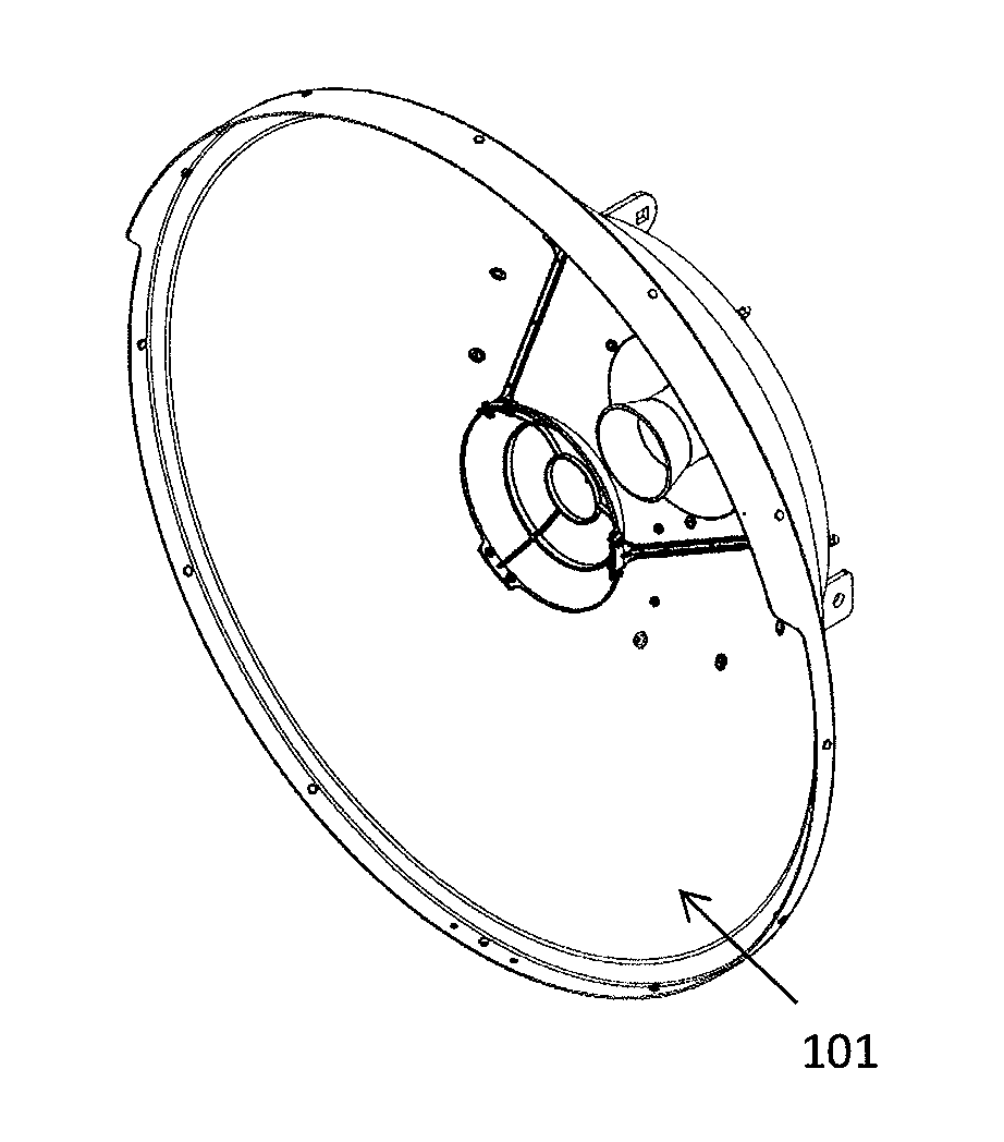
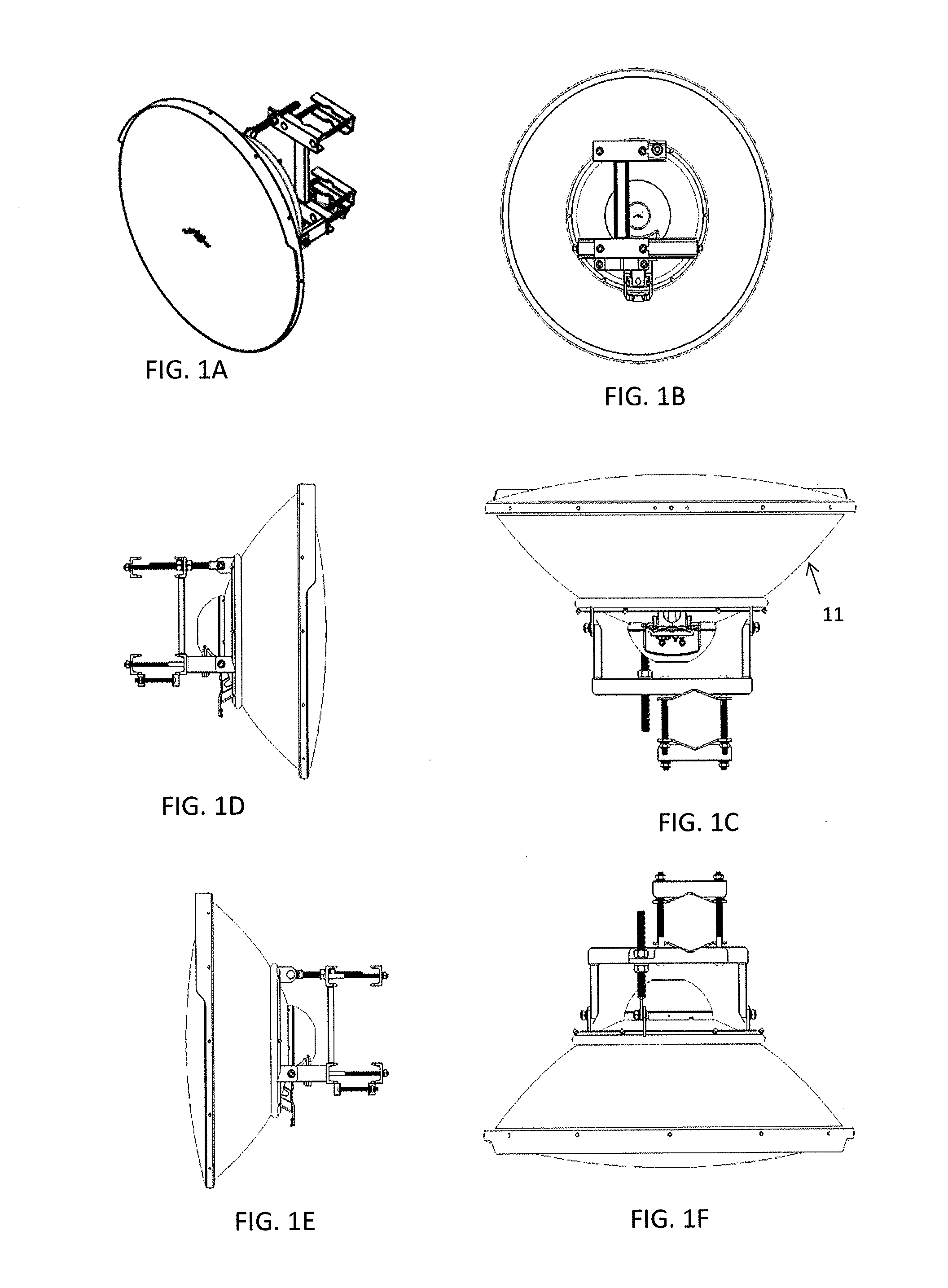
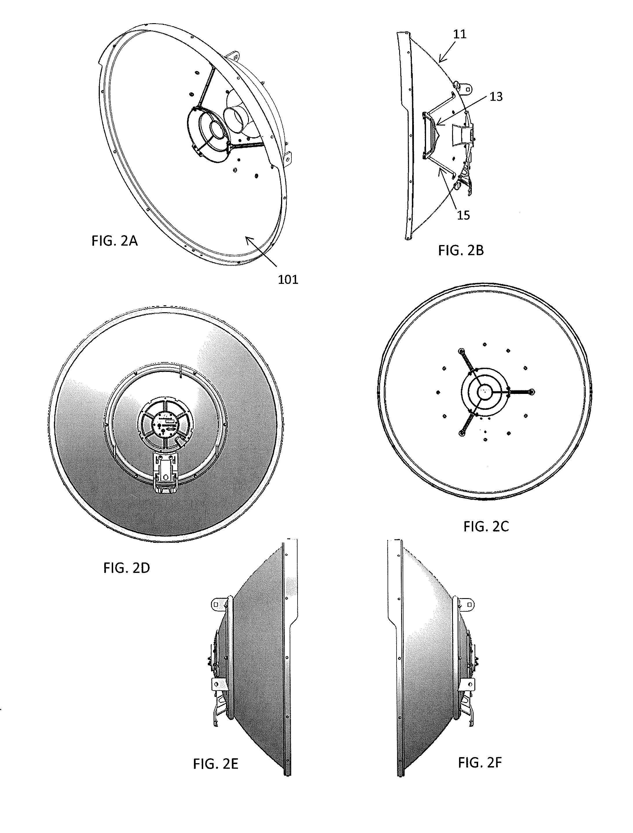
[0092]In general, described herein are wireless antenna assemblies, including transmission stations, which may include a radio and antenna (e.g. combined radio and antenna), for providing wireless broadband access configured for outdoor and / or indoor use to provide point-to-point or point-to-multipoint communication. Also described herein are antennas that may be used as part of a wireless transmission station.

[0093]A wireless transmission station apparatuses, including devices and / or apparatuses, may include a closed housing that may be sealed or otherwise made weatherproof / waterproof, an integrated bracket mount forming part of the housing, and an internal space housing one or more reflectors, and an emitter (e.g., a primary feed having a single emitter surface that receives input from multiple antenna feeds each carrying a differently polarized RF signal. In some variations, the device also includes a bracket the engages (and may be locked / secured) to the bracket mount on the rea...


PUM


Abstract

Antenna assemblies are described herein. Any of these assemblies may include a primary feed that includes a single patterned emitting surface from which multiple different beams of RF signals are emitted corresponding to different antenna input feeds each communicating with the patterned antenna emitting surface. The antenna assembly may include a primary reflector, a secondary reflector, and a primary feed that is feed by multiple antenna input feeds so that different regions of the primary and secondary antenna correlate with different beams emitted by the primary feed. The antenna assembly is capable of emitting beams in the same direction having different polarizations using a single primary feed. Also described herein are methods of operating an antenna assembly. Access point devices that have a single primary feed configured to emit multiple beams are also described.

Description

CROSS REFERENCE TO RELATED APPLICATIONS[0001]This patent application claims priority to each of the following U.S. provisional patent applications: U.S. Provisional Patent Application No. 61 / 973,750, filed Apr. 1, 2014, titled “ANTENNA ASSEMBLY;” U.S. Provisional Patent Application No. 61 / 978,755, filed Apr. 11, 2014, titled “ANTENNA ASSEMBLY;” and U.S. Provisional Patent Application No. 62 / 073,833, filed Oct. 31, 2014, titled “MULTI-FOCAL POINT ANTENNA ASSEMBLIES.” Each of these provisional patent applications is herein incorporated by reference in its entirety.INCORPORATION BY REFERENCE[0002]All publications and patent applications mentioned in this specification are herein incorporated by reference in their entirety to the same extent as if each individual publication or patent application was specifically and individually indicated to be incorporated by reference.FIELD[0003]Described herein are wireless radio and antenna apparatuses and methods that may form part of a broadband ...

Claims


Application Information

Patent Timeline
IPC IPC(8): H01Q25/00H01Q1/42H01Q13/02H01Q15/16H01Q21/24
CPCH01Q25/00H01Q15/16H01Q1/421H01Q13/02H01Q21/245H01Q1/42H01Q19/19H01Q1/06H01Q9/0421H01Q13/0258H01Q1/405H01Q25/001H01Q25/04H01Q19/193
Inventor SANFORD, JOHN R.LEE, JUDESUN, YANWEI
Owner UBIQUITI INC
Why Eureka
Try Eureka