
Distributed base station, communication system, and signal transmission method thereof

Active Publication Date: 2007-04-26
ALCATEL LUCENT SAS
View PDF8 Cites 186 Cited by
  • Summary
  • Abstract
  • Description
  • Claims
  • Application Information

AI Technical Summary

Benefits of technology

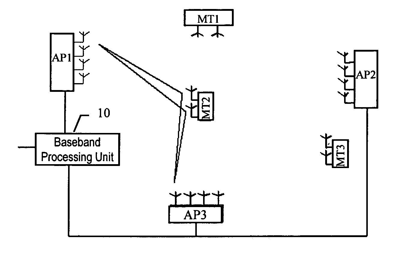
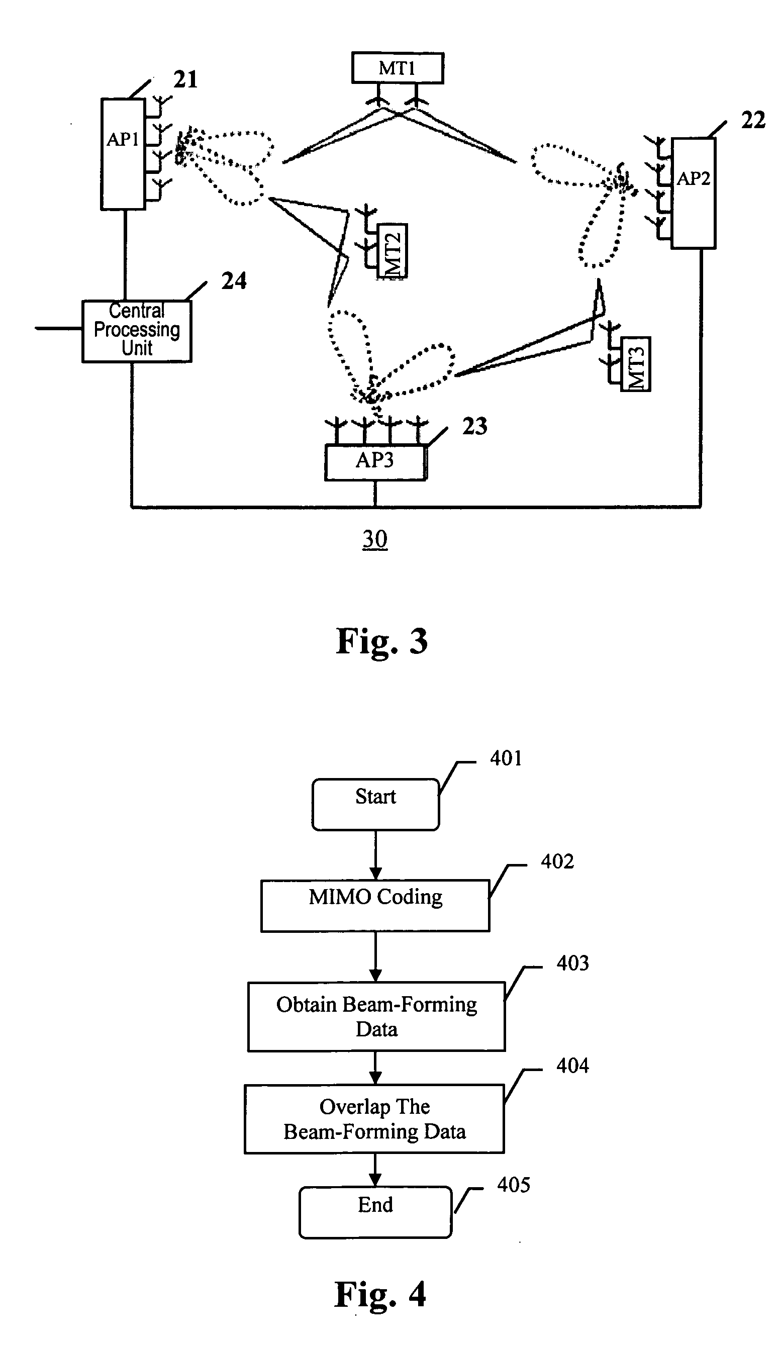
[0012] In view of the problem that the system capacity in a distributed structure using MIMO channel is restricted, the present invention proposes a distributed base station by making reference to the above technologies for improving the system capacity. The base station simultaneously occupies the same wireless channel resources and communicates with multiple adjacent mobile stations with one or more distributed antenna-RF processing unit of the base station. In order to avoid multiple access interference between the mobile stations, the mobile stations are spaced through beam-forming processing. Several beams pointing to the mobile station and multiple antennas on the mobile station further constitute MIMO transmission to raise transmission rate of the mobile station.
[0016] Due to the adoption of SDMA multiple access mode that multiple remote antenna-RF processing units perform joint processing, the distributed base station, communication system and signal transmission method of the present invention can effectively reduce interference between mobile stations, so that it becomes possible for multiple mobile stations to simultaneously perform transmission using the same channel resources, and the overall system capacity is raised.

Problems solved by technology

Thus, how to design systems with high peak transmission rate and high capacity has become a huge challenge.
However, as spectrum resources get increasing limited, future mobile communication systems might resort to a higher frequency band, such as the frequency band of 5 GHz.
Therefore, whether or not conventional cellular network structures can be adopted and new architectures can be designed in future systems so as to meet future systems' demands becomes a problem that is worthy of careful consideration.
This is a major problem restricting MIMO applications.
This severely restricts the system capacity.

Method used


Image

  • Distributed base station, communication system, and signal transmission method thereof
  • Distributed base station, communication system, and signal transmission method thereof
  • Distributed base station, communication system, and signal transmission method thereof

Examples


Embodiment Construction

[0022] Referring to the accompanying drawings, embodiments of the present invention will be described in detail.

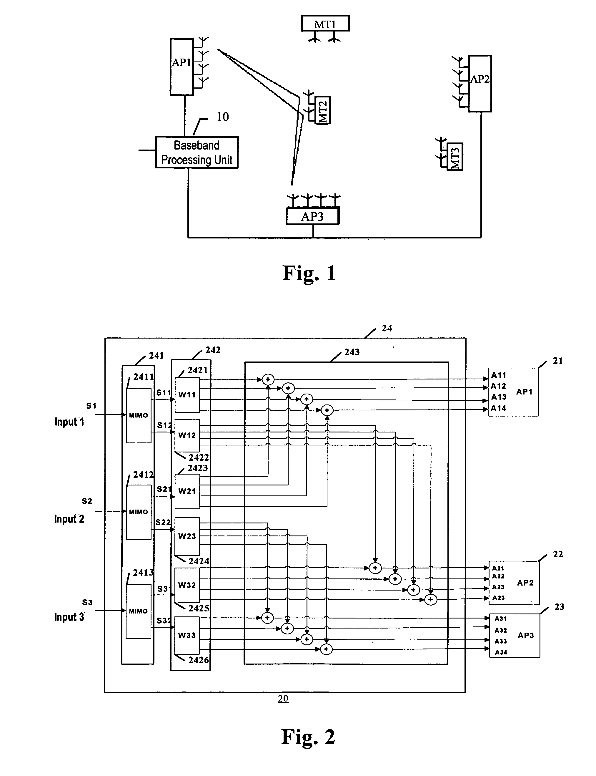
[0023]FIG. 2 shows a schematic layout view of a distributed base station according to the present invention. For the purpose of convenience, the embodiment of the present invention is explained by taking the following situation as an example: a distributed base station 20 adopts three remote antenna-RF processing units 21, 22 and 23 each of which is provided with four antennas. Referring to FIG. 3, service is simultaneously provided to three mobile stations MT1, MT2 and MT3 each of which is provided with two antennas, by using the distributed base station 20 as shown in FIG. 2. Here, the system adopts a 2×2 MIMO solution, in which the antenna-RF processing units 21 and 22 are selected to form two beams which form MIMO in conjunction with MT2, and the antenna-RF processing units 22 and 23 are selected to form two beams which form MIMO in conjunction with MT3.

[0024] As sho...


PUM


Abstract

The present invention discloses a distributed base station serving mobile stations, which comprises multiple antenna-RF processing units and a central processing unit remotely connected with said multiple antenna-RF processing units. Each of the antenna-RF processing units has an antenna array formed by multiple antennas. Said central processing unit comprises: an MIMO coding unit for MIMO coding of data of each of the mobile stations so that data of each of the mobile stations generates multi-path data symbols; a beam-forming unit for multiplying each path data symbol of the multi-path data symbols of each of the mobile stations by a weighted coefficient vector corresponding to this path data symbol, to obtain beam-forming data of each path data symbol of each of the mobile stations; and an overlapping unit for, with respect to each antenna in said antenna-RF processing units, overlapping beam-forming data of the respective mobile stations for this antenna and feeding the overlapped beam-forming data to this antenna for transmission. The present invention further discloses a communication system having the above distributed base station and the corresponding signal transmission method.

Description

CROSS-REFERENCE TO RELATED APPLICATIONS [0001] This application is entitled to the benefit of Chinese Patent Application No. CN200510030624.9 filed on Oct. 18, 2005 with the Chinese Patent Office. FIELD OF THE INVENTION [0002] The present invention relates to Multiple Input Multiple Output (MIMO) transmission, and particularly to a distributed-structured base station that performs transmission using Multiple Input Multiple Output (MIMO) channels, a communication system having the base station, and a signal transmission method used in the aforesaid base station and communication system. BACKGROUND OF THE INVENTION [0003] The development of mobile communication services imposes higher requirements on the transmission capability of air interfaces of future wireless communication systems. Thus, how to design systems with high peak transmission rate and high capacity has become a huge challenge. [0004] In order to utilize limited radio frequency resources more effectively, the Time Divis...

Claims


Application Information

Patent Timeline
IPC IPC(8): H04M1/00H04J99/00
CPCH04B7/022H04B7/0452H04B7/0669H04B7/068
Inventor CAI, LIYU
Owner ALCATEL LUCENT SAS
Learn More