
Nuclear reactor internals alignment configuration

a technology for nuclear reactors and alignment configurations, applied in nuclear reactors, nuclear elements, greenhouse gas reduction, etc., can solve the problems of difficult removal of the core shroud assembly, protruding alignment pins,

Active Publication Date: 2009-11-10
WESTINGHOUSE ELECTRIC CORP
View PDF7 Cites 2 Cited by
  • Summary
  • Abstract
  • Description
  • Claims
  • Application Information

AI Technical Summary

Benefits of technology

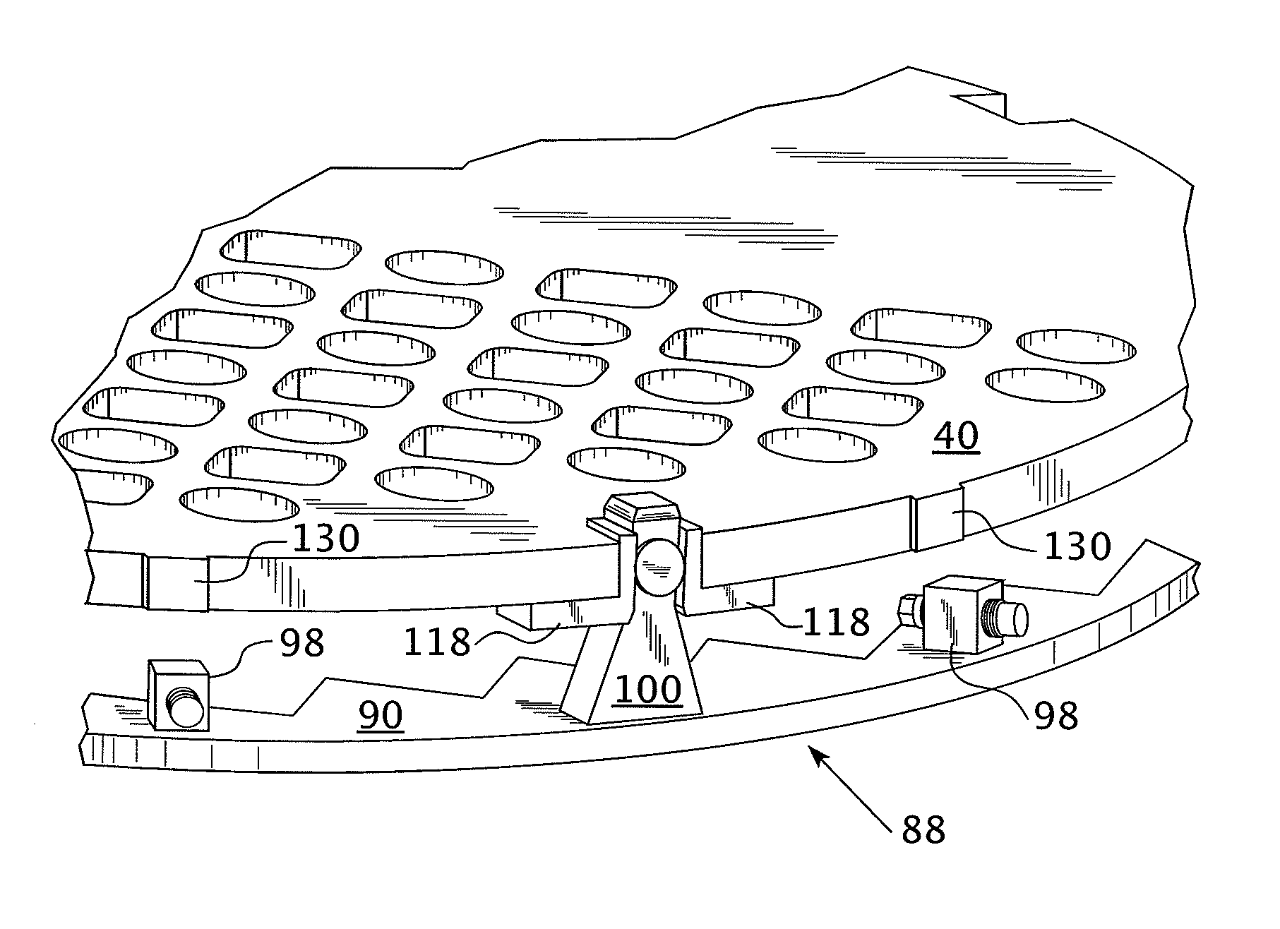
[0014]During installation of the upper internals over the lower internals, chamfered lead-in surfaces on the alignment posts will assure proper alignment of the upper core plate inserts prior to engagement of upper core plate fuel guide pins with the fuel assembly top nozzles. Preferably radial guides or bumpers extend from the peripheral surface on the outside diameter of the upper core plate, that are spaced circumferentially to provide additional guidance for the upper core plate within the lower internals core barrel during installation. The thickness of these bumpers may also be customized so that the in-plane loading of the upper core plate during reactor operation can be transferred as a radial load to the core barrel.

Problems solved by technology

This is particularly challenging when one considers the thermal expansion and contraction that has to be accommodated through power ramp-up and cool down sequences, where temperatures can vary between 50° F.
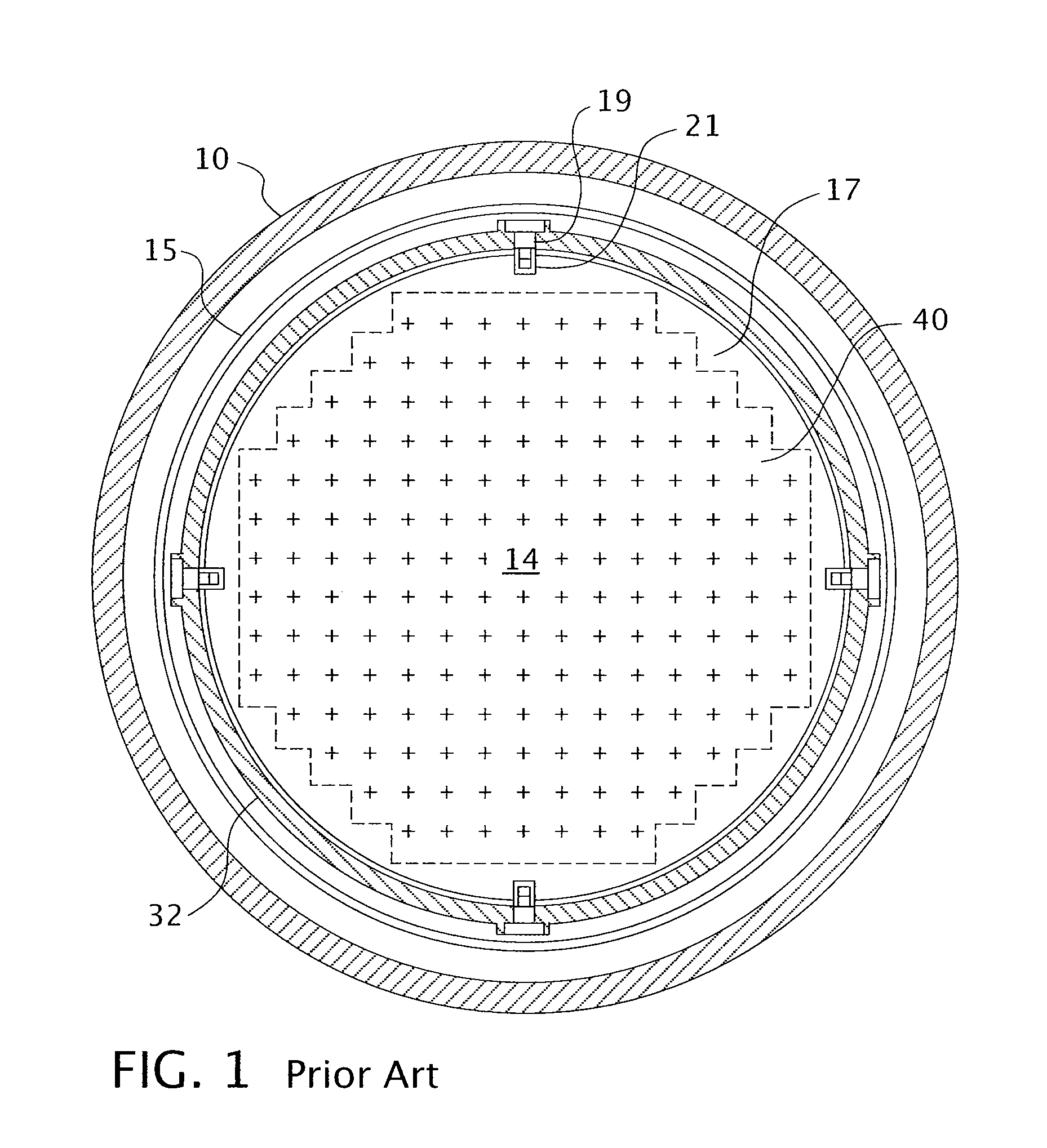
In this arrangement, it is not possible to have protruding alignment pins (19) to engage the upper internal's core plate.
In view of the installation sequence for installing the alignment plates, it's likely that it may be difficult to remove the core shroud assembly, should there be a need during the 60 year design life of the advance passive plant designs.

Method used


Image

  • Nuclear reactor internals alignment configuration
  • Nuclear reactor internals alignment configuration
  • Nuclear reactor internals alignment configuration

Examples


Embodiment Construction

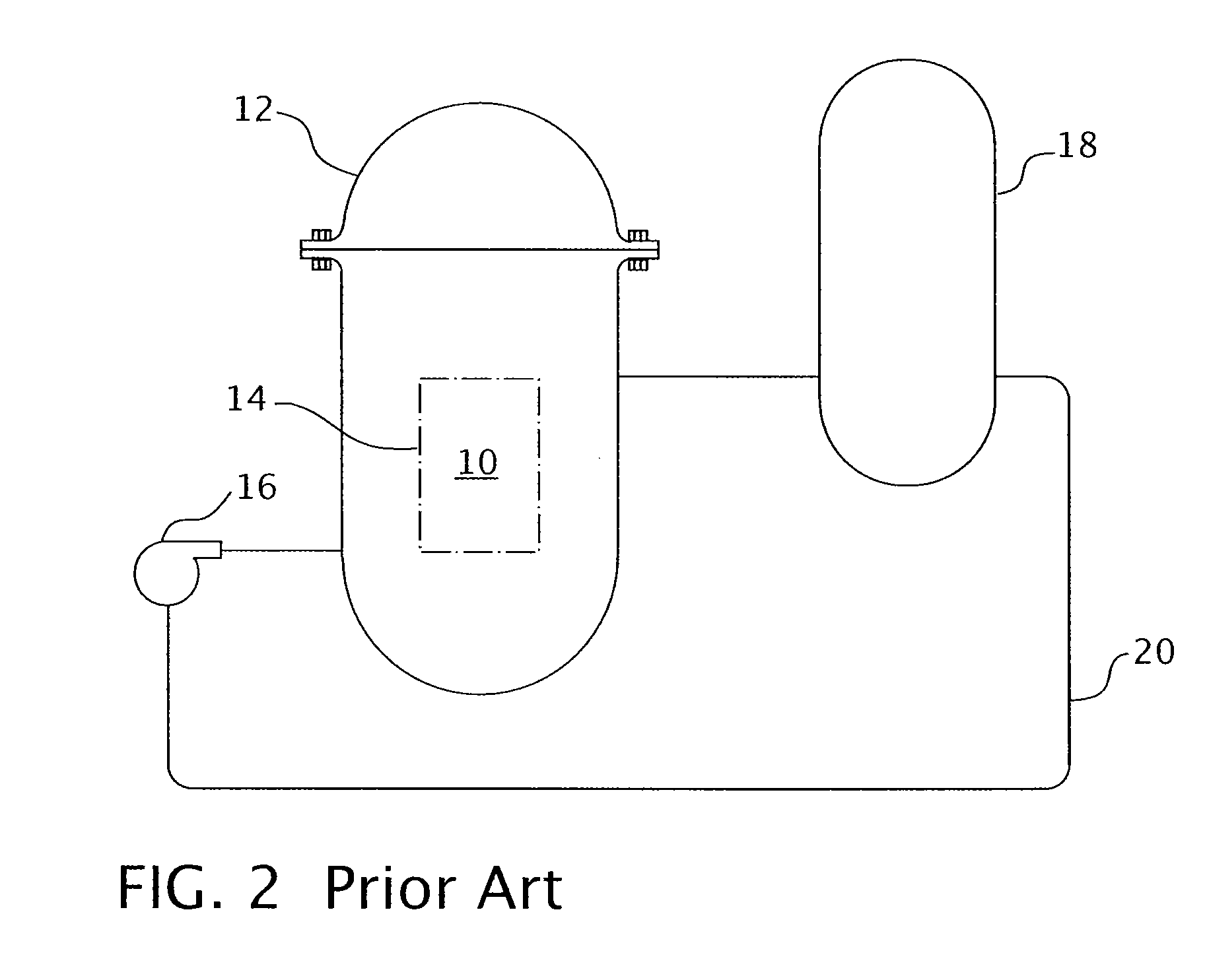
[0034]Referring now to the drawings, FIG. 2 shows a simplified nuclear reactor primary system, including a generally cylindrical reactor pressure vessel (10) having a closure head (12) enclosing a nuclear core (14). A liquid reactor coolant, such as water, is pumped into the vessel (10) by pumps (16) through the core (14) where heat energy is absorbed and is discharged to a heat exchanger (18), typically referred to as a steam generator, in which heat is transferred to a utilization circuit (not shown), such as a steam-driven turbine generator. The reactor coolant is then returned to the pump (16), completing the primary loop. Typically, a plurality of the above-described loops are connected to a single reactor vessel (10) by reactor coolant piping (20).

[0035]An exemplary reactor design is shown in more detail in FIG. 3. In addition to a core (14) comprised of a plurality of parallel, vertical co-extending fuel assemblies (22), for purposes of this description, the other vessel inte...


PUM


Abstract

An alignment system that employs jacking block assemblies and alignment posts around the periphery of the top plate of a nuclear reactor lower internals core shroud to align an upper core plate with the lower internals and the core shroud with the core barrel. The distal ends of the alignment posts are chamfered and are closely received within notches machined in the upper core plate at spaced locations around the outer circumference of the upper core plate. The jacking block assemblies are used to center the core shroud in the core barrel and the alignment posts assure the proper orientation of the upper core plate. The alignment posts may alternately be formed in the upper core plate and the notches may be formed in top plate.

Description

GOVERNMENT INTEREST[0001]This invention was made with government support under Contract No. DE-FC07-05ID14636 awarded by the Department of Energy. The government has certain rights in this invention.BACKGROUND OF THE INVENTION[0002]1. Field of the Invention[0003]The present invention relates generally to nuclear reactor internals and more specifically to apparatus for maintaining the alignment of the nuclear reactor internals.[0004]2. Description of the Prior Art[0005]The primary side of nuclear reactor power generating systems which are cooled with water under pressure comprises a closed circuit which is isolated from and in heat-exchange relationship with a secondary side for the production of useful energy. The primary side comprises the reactor vessel enclosing a core internals structure that supports a plurality of fuel assemblies containing fissile material, the primary circuit within heat exchange steam generators, the inner volume of a pressurizer, pumps and pipes for circul...

Claims


Application Information

Patent Timeline
Patent Type & Authority Patents(United States)
IPC IPC(8): G21C1/04B65G21/20F16D1/06G21C23/00G21C9/00
CPCG21C13/024G21C19/19G21Y2002/202Y10T403/7041Y02E30/40Y10T403/5741G21Y2004/30Y02E30/30
Inventor GILMORE, CHARLES B.SINGLETON, NORMAN R.
Owner WESTINGHOUSE ELECTRIC CORP
Learn More