Depth fused display

a display and depth technology, applied in the field of depth display, can solve the problems of rapid detection by preattentive processing, timeframe is insufficient for a human to consciously decide, and research shows that these may not be detected preattentively, so as to reduce the effect of parallax, enhance the viewing angle of the display, and enhance the display's usability

Inactive Publication Date: 2009-11-17
APTIV TECH LTD
View PDF149 Cites 88 Cited by
  • Summary
  • Abstract
  • Description
  • Claims
  • Application Information

AI Technical Summary

Benefits of technology

[0064]A further advantage of the present invention relates to the existing problem of parallax error created by viewing the composite image from an off-fixation axis angle. Existing combination displays suffer from pronounced parallax effects for off-axis viewing due to the degree of physical separation between the two displays.
[0065]Any means of increasing the acceptable viewing angle of a display greatly enhances the display's usability. Whilst viewing a display, particularly computer monitors and the like, from large off axis angles is unusual, it is entirely normal for a viewer to move their viewpoint to a limited degree.
[0066]Parallax error reduces the effects of ‘depth fusion’ as this implicitly requires the images on different screens to be substantially aligned. The effects of parallax are reduced by the present invention by two features.
[0067]Firstly, reducing the physical separation between displays by physically stacking in an overlapping alignment produces a significant reduction in parallax in comparison to that of ‘combination displays’ as described above.
[0068]Secondly, in a further embodiment, parallax effects are attenuated by interposing a refractor between the said imaging screens.
[0069]Preferably, said refractor has a greater refractive index than air. It is possible, the display may be operated in a medium other than air, in which case, said refractor has a refractive index greater than that of said medium.

Problems solved by technology

When viewing a large number of visual elements, certain variations or properties in the visual characteristics of elements can lead to rapid detection by preattentive processing.
This timeframe is insufficient for a human to consciously decide to look at a different portion of the scene.
However, if the target is composed of a conjunction of unique features, i.e. a conjoin search, then research shows that these may not be detected preattentively.
Using the above examples, if a target is comprised for example, of a red circle set within distractors including blue circles and red squares, it is not possible to detect the red circle preattentively as all the distractors include one of the two unique features of the target.
In comparison, if the constituent elements of the above described cubes are re-orientated to remove the apparent three dimensionality, subjects cannot preattentively detect targets which have been inverted for example.
Unfortunately, each of these possesses certain limitations.
Head-mounted displays add ergonomic inconvenience, reduce the viewer's peripheral awareness and are often cumbersome and can cause nausea, headaches and / or disorientation.
Lenticular displays are only really effective at oblique viewing angles and holography is currently limited to displaying static images.
Such systems are unavoidably bulky and cumbersome in comparison to conventional single screen displays in order to house the two separate displays without any physical overlap.
Additional difficulties arise from the generation of a parallax error proportional to the distance between the image planes, which is exacerbated by increasing the display separation to increase the ‘depth’ of the scene perceived by the viewer.
Conversely, if the displays are brought into close proximity, moiré interference effects mar the resultant image.

Method used


Image

  • Depth fused display
  • Depth fused display
  • Depth fused display

Examples


Embodiment Construction

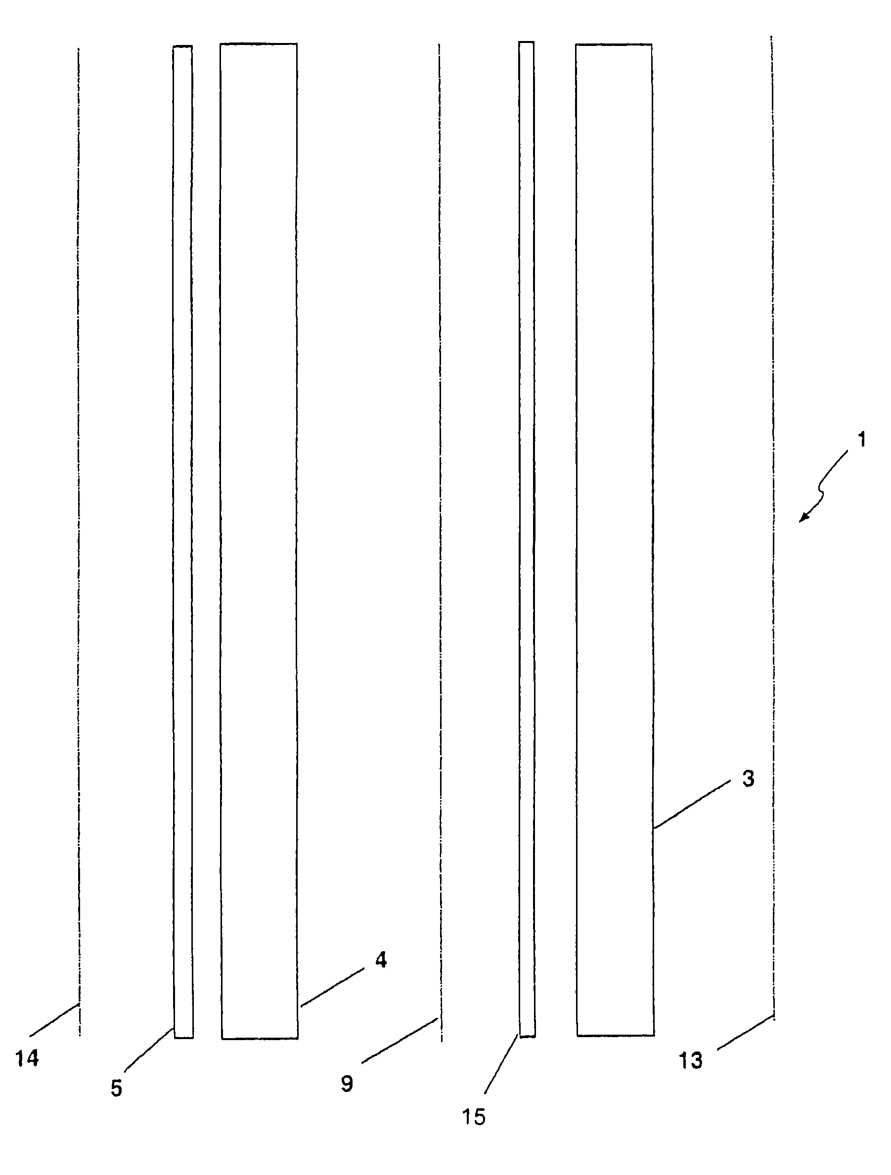
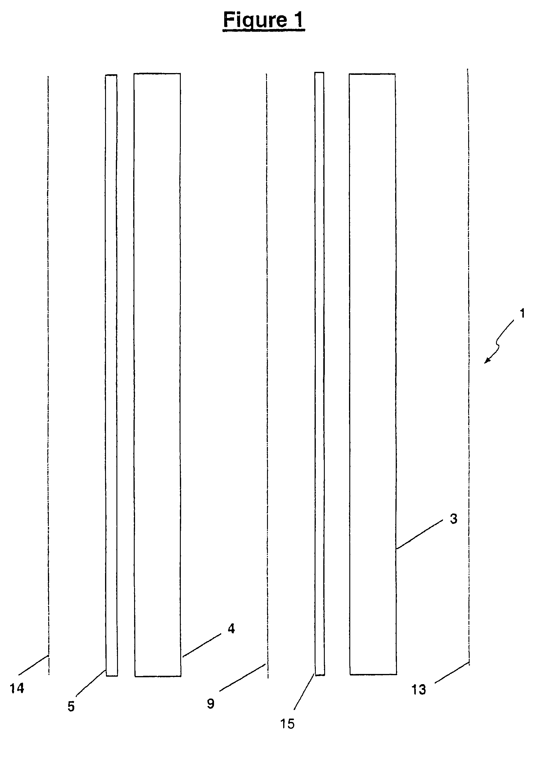
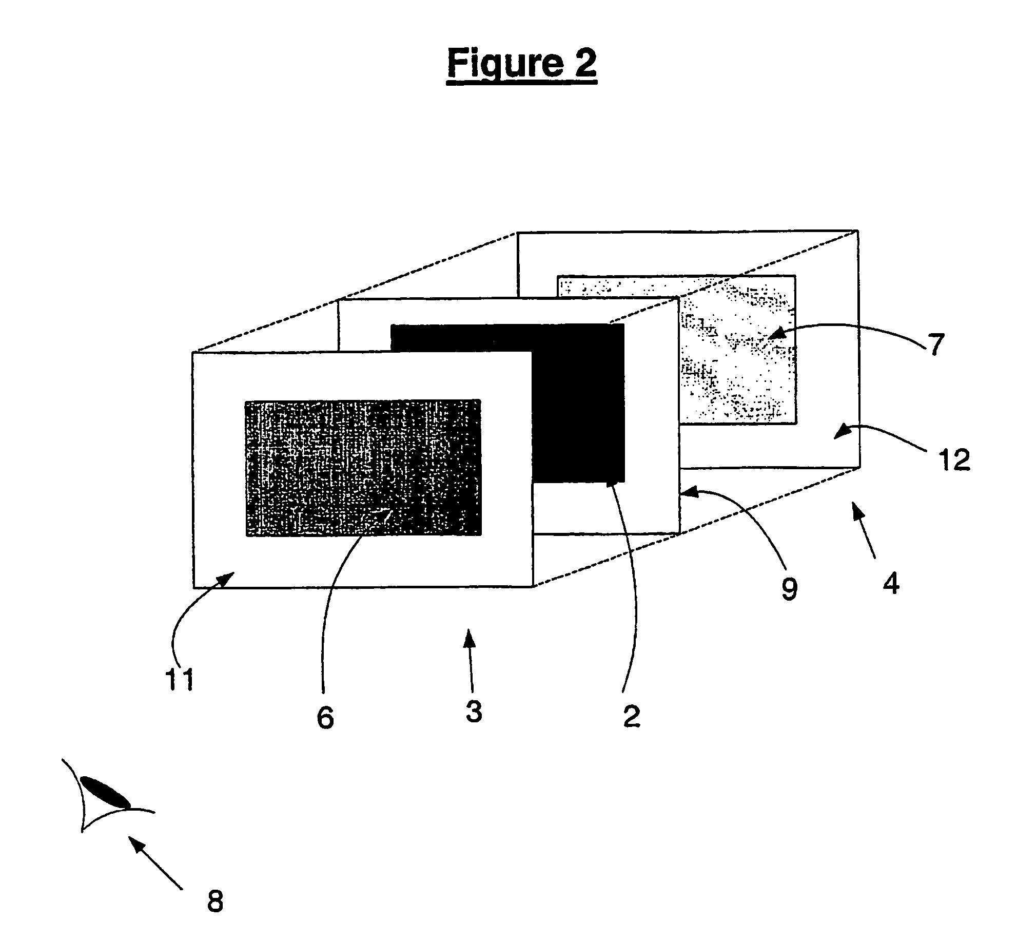
[0089]The FIGS. 1-4 illustrate preferred embodiments of the present invention in which a display (1) capable of displaying a variable depth image (2) is composed of a plurality of transparent imaging screens in the form of LCD screens (3), parallel to, but spaced apart from each other and to a rear display screen (4) provided with a backlight (5). It should be apparent to one skilled in the art that a number of alternative display technologies may be utilised in place of the LCD screens. Furthermore, although FIG. 1 shows a single screen (3) in front of the rear display (4) for the sake of clarity and convenience, any number of additional (at least partially transparent) imaging screens (3) may be incorporated. Such displays provide a three dimensional quality the scene viewed by an observer, as described in the applicants co-pending patents PCT No. PCT / NZ98 / 00098 and PCT / NZ99 / 00021, incorporated by reference herein.

[0090]Although, as previously stated, the present invention is not ...


PUM

PropertyMeasurementUnit
threshold timeaaaaaaaaaa
response timeaaaaaaaaaa
luminanceaaaaaaaaaa

Abstract

A method of displaying an image with variable perceived depth using a display (1) including one or more at least partially transparent, substantially parallel imaging screens (3) located in front of, and overlapping with, a rear imaging screen (4),characterized in that a physical image is formed on two or more imaging screens (3,4), each image being of substantially identical configuration and being sized and aligned such that like portions of each image are coterminous to a viewer observing the display,wherein at least two of said coterminous images are displayed with different luminance.

Description

CROSS-REFERENCE TO RELATED APPLICATIONS[0001]The present patent application is a continuation of prior PCT Patent Application No. PCT / NZ02 / 00243, filed on Nov. 11, 2002, which claims priority from New Zealand Patent Application No. 515395, filed on Nov. 9, 2001.TECHNICAL FIELD[0002]The present invention relates to a variable depth display and more particularly to use of luminance differences between images located on separate screens as the means of varying the perceived depth.BACKGROUND ART[0003]The ability to form images at different depths within a display, whether real or perceived, has been the subject of significant and ongoing research and development in the quest to provide display technology capable of replicating or augmenting the depth effects conferred by normal human sight.[0004]Three-dimensional or multi-focal plane displays are known to provide numerous advantages or capabilities unavailable with conventional two-dimensional displays. The manner in which human beings ...

Claims


Application Information

Patent Timeline
Patent Type & Authority Patents(United States)
IPC IPC(8): G09G5/00G02F1/13H04N13/04H04N13/395
CPCG09G3/003H04N13/0495G09G3/20G09G2300/023H04N13/395
Inventor BELL, GARETH PAULENGEL, GABRIEL DAMONSEARLE, MARK JOHN
Owner APTIV TECH LTD
Why Eureka
Try Eureka